
Real time detection of loss of cantilever sensing loss

a technology of loss detection and real-time detection, applied in the field of surface image measurement, can solve the problems of inherently slow present methods, inability to and current measurement techniques that do not meet the aforementioned high precision and bandwidth requirements

Inactive Publication Date: 2008-01-01
IOWA STATE UNIV RES FOUND
View PDF3 Cites 4 Cited by
  • Summary
  • Abstract
  • Description
  • Claims
  • Application Information

AI Technical Summary

Benefits of technology

This approach enhances interrogation speeds by two orders of magnitude and allows for real-time detection of cantilever-sample interaction, reducing erroneous data and increasing bandwidth in nanotechnological studies.

Problems solved by technology

In spite of the underlying promise, considerable challenges remain.
Current measurement techniques do not meet the aforementioned high precision and bandwidth requirements.
The present methods are therefore inherently slow owing to the large settling times of the cantilever oscillations.
In the ESM imaging mode, the feedback is essentially ineffective and the amplitude is used as the imaging parameter.
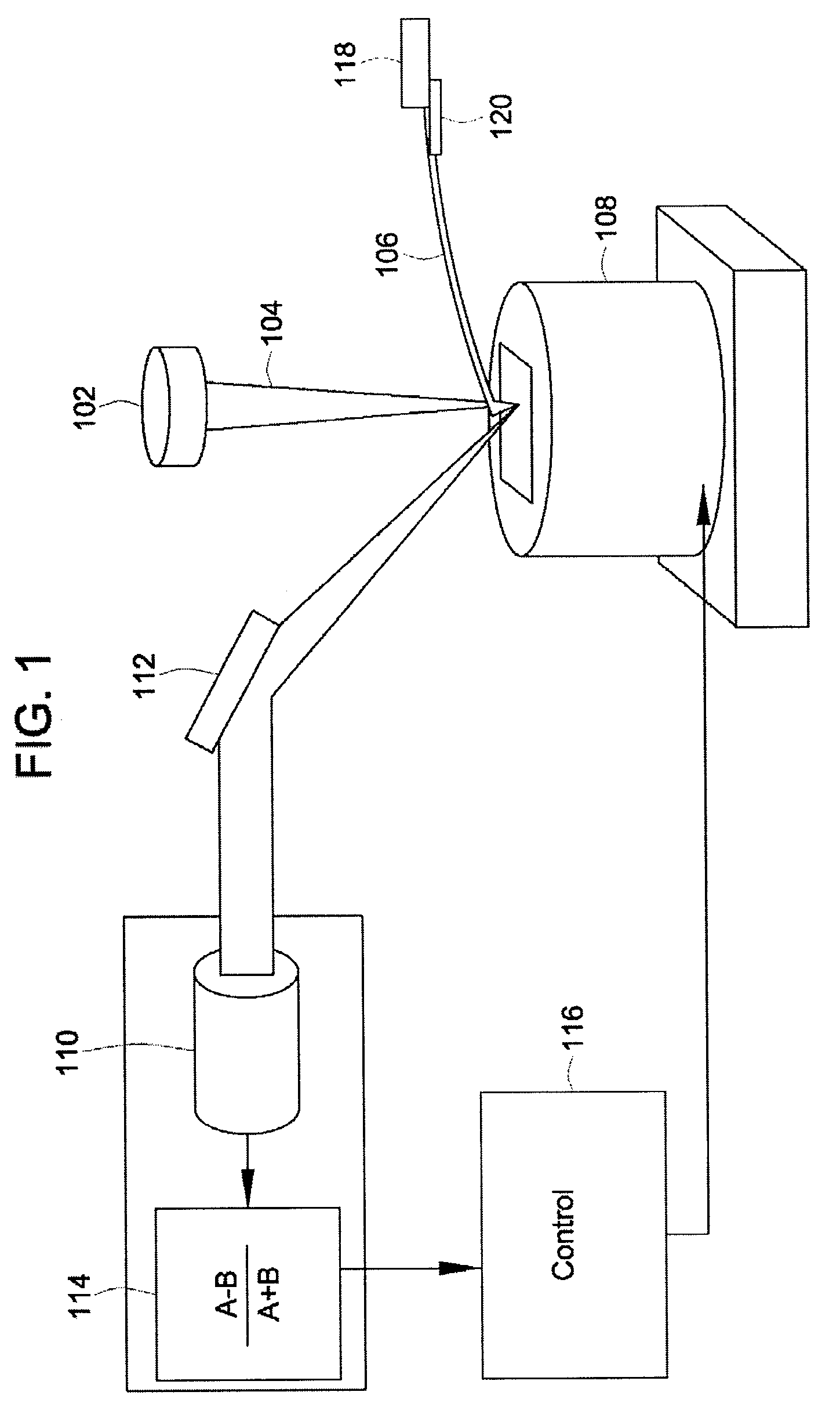
A fundamental drawback that is common to these and other deflection based imaging schemes is that when the cantilever loses its interaction with the sample, it is not possible to glean any information about the sample from the cantilever deflection.
This leads to erroneous interpretation of images and data, where a loss of interaction is often interpreted as a manifestation of a sample feature.

Method used


Image

  • Real time detection of loss of cantilever sensing loss
  • Real time detection of loss of cantilever sensing loss
  • Real time detection of loss of cantilever sensing loss

Examples


Embodiment Construction

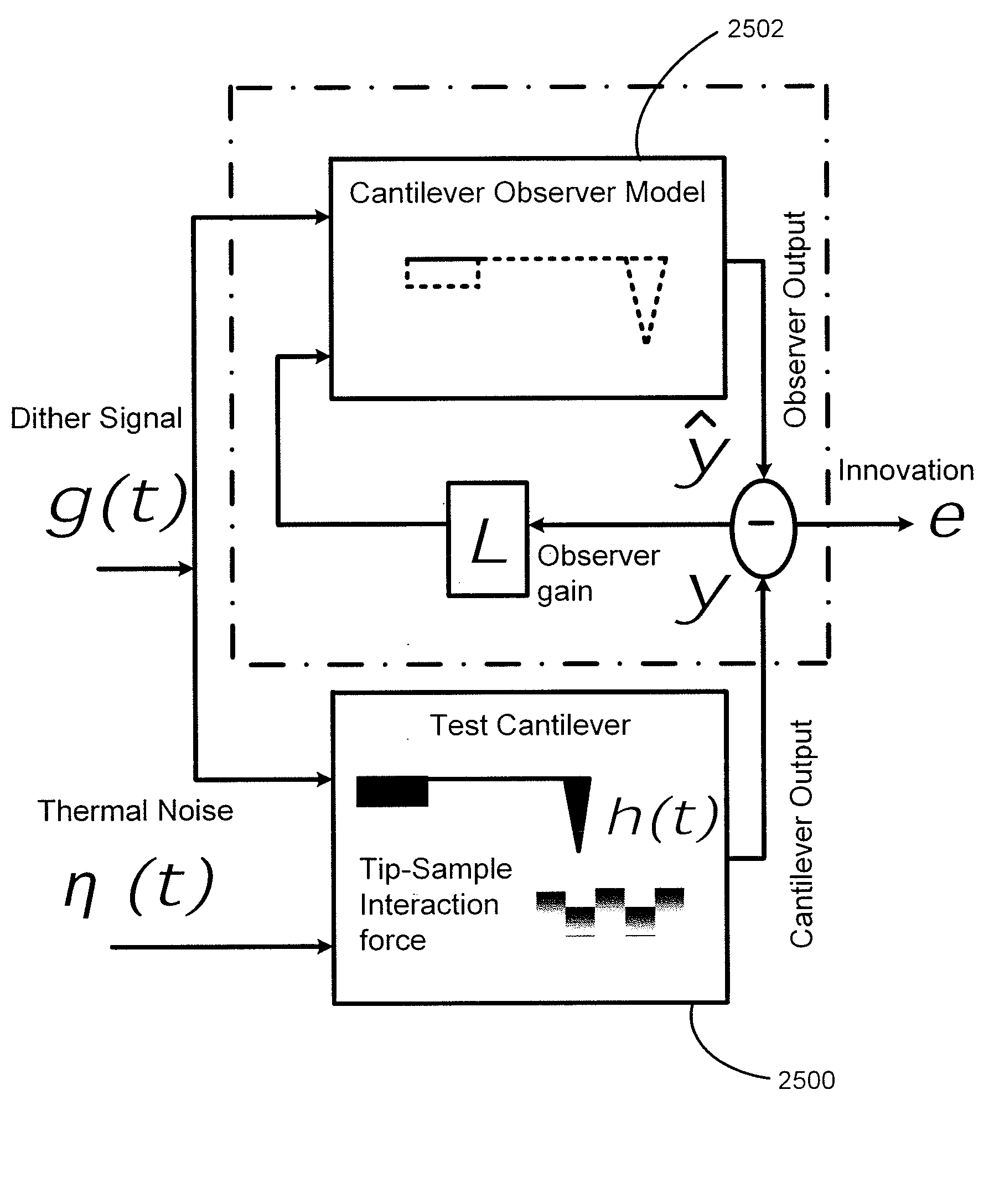
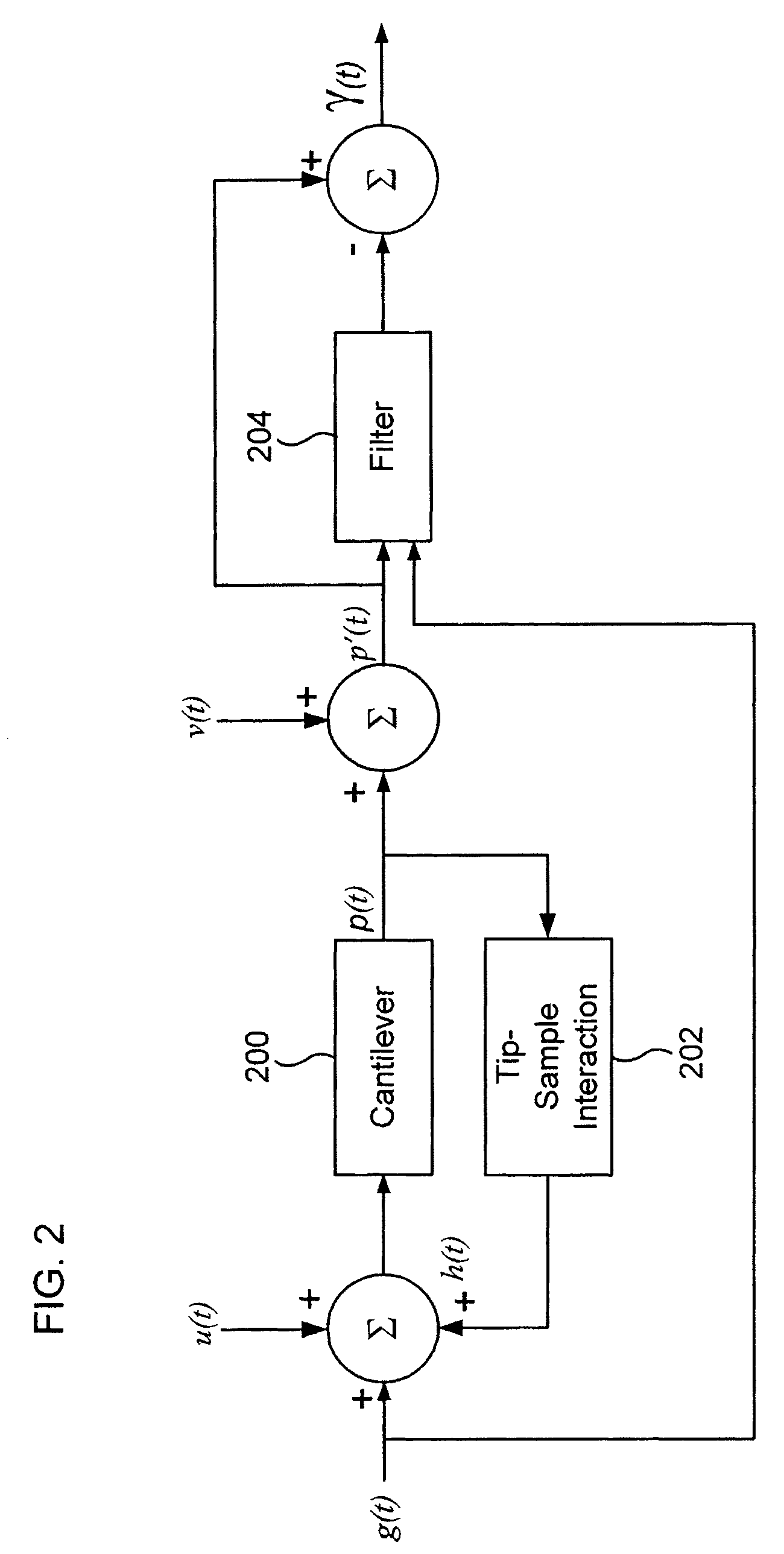
[0047]The invention provides a method to utilize the transient behavior of the cantilever oscillations for sample imaging and detection. The transient based methods of the invention improve performance of interrogation speeds by approximately two orders of magnitude over steady state based methods. Fundamental limitations due to high quality factors are removed using the transient part of the cantilever motion. A model of the cantilever is used to build an observer that is used to estimate the state of the cantilever dynamics. The cantilever-sample interaction is modeled and corresponding data during the transient state of the probe is analyzed using generalized likelihood ratio test to detect and probe the sample profile. The use of the transient data results in sample detection at least ten times faster than using the steady state data based methods. In the description that follows, an AFM shall be used to describe the invention. While an AFM shall be used, the invention may be us...


PUM


Abstract

An approach to detect when a cantilever loses interaction with a sample, thereby detecting when a portion of an image obtained using a cantilever is spurious is presented. An observer based estimation of cantilever deflection is compared to the cantilever deflection and the resulting innovation is used to detect when the cantilever loses interaction. The loss of interaction is determined when the innovation is outside of and / or below a threshold level.

Description

CROSS-REFERENCE TO RELATED PATENT APPLICATIONS[0001]This patent application is a continuation-in-part of U.S. patent application Ser. No. 10 / 953,195, filed Sep. 29, 2004 now U.S. Pat. No. 7,066,014, which claims the benefit of U.S. Provisional Patent Application No. 60 / 507,409, filed Sep. 30, 2003, the entire disclosures which are incorporated by reference in their entirety herein.STATEMENT REGARDING FEDERALLY SPONSORED RESEARCH AND DEVELOPMENT[0002]This invention was made in part with Government support under Grant Number ECS-0330224 awarded by the National Science Foundation. The Government may have certain rights in this invention.FIELD OF THE INVENTION[0003]This invention pertains to surface image measurements and more particularly relates to imaging of surfaces using microcantilevers that are the main probes in atomic force microscopes.BACKGROUND OF THE INVENTION[0004]Imaging and detection of structure surfaces using cantilevers have been in use for decades. For example, one pr...

Claims


Application Information

Patent Timeline
Patent Type & Authority Patents(United States)
IPC IPC(8): G01B5/28G02B6/26G01Q10/00G01Q10/06G01Q20/02G01Q30/04G01Q60/24G01Q60/32
CPCB82Y35/00G01Q10/06G01Q20/02G01Q30/04G01Q60/32
Inventor SALAPAKA, MURTI V.DE, TATHAGATAAGARWAL, PRANAVSAHOO, DEEPAK RANJAN
Owner IOWA STATE UNIV RES FOUND
Learn More