
Head-up display

a display and head-up technology, applied in the field of head-up displays, can solve the problems that the arrangement shown exhibits scarce suitability for use in the head-up display, and achieve the effects of low overall size, low weight and low power loss

Active Publication Date: 2007-12-25
OSRAM OLED
View PDF13 Cites 30 Cited by
  • Summary
  • Abstract
  • Description
  • Claims
  • Application Information

AI Technical Summary

Benefits of technology

[0007]It is therefore an object of the invention to produce a light flux with the aid of devices that exhibit, in particular, a low overall size and low weight, consume, and / or output as heat, as little power loss as possible, and are therefore also suitable for operation in a vehicle.
[0010]A cost effective fabrication of the device according to the invention is possible when the positive lenses of all the light channels are integrally connected to a plate arranged between the light source and the grid reflector. However, this plate permits an undesired conduction of light in a transverse direction, and this can be prevented when the positive lenses are integrally connected in groups to webs arranged between the light source and the grid reflector.
[0011]An advantageous refinement of the invention consists in that the radii of curvature of the lens differ in different directions (astigmatic lenses). The light distribution can thereby be improved, particularly in elongated light exit openings.
[0012]The image reproduction apparatus including light valves and arranged at the light exit opening permits a compact device for producing high-resolution images of high luminous density and with a uniform distribution of luminous density over the entire image area. The device for focusing and scattering ensures in this case that the light produced by the light-emitting diodes is concentrated onto the surface of the image reproduction apparatus without the individual light emitting diodes being disturbingly imaged. A preferred field of application of the device according to the invention are graphical head up displays for vehicle applications.
[0013]The image reproduction apparatus lends the device according to the invention a few more advantages, which are set forth below. Thus, the coordination between RGB light source and color display renders possible the display of graphic color images in a head up display in conjunction with adequate luminous density. A uniform distribution of color and luminous density of the background lighting on the area of the liquid crystal display is achieved in cooperation with the reflector and the lens.

Problems solved by technology

However, the arrangements shown exhibit scarcely any suitability for use in a head-up display, because of their respective focusing and scattering characteristics.

Method used


Image

  • Head-up display
  • Head-up display
  • Head-up display

Examples


Embodiment Construction

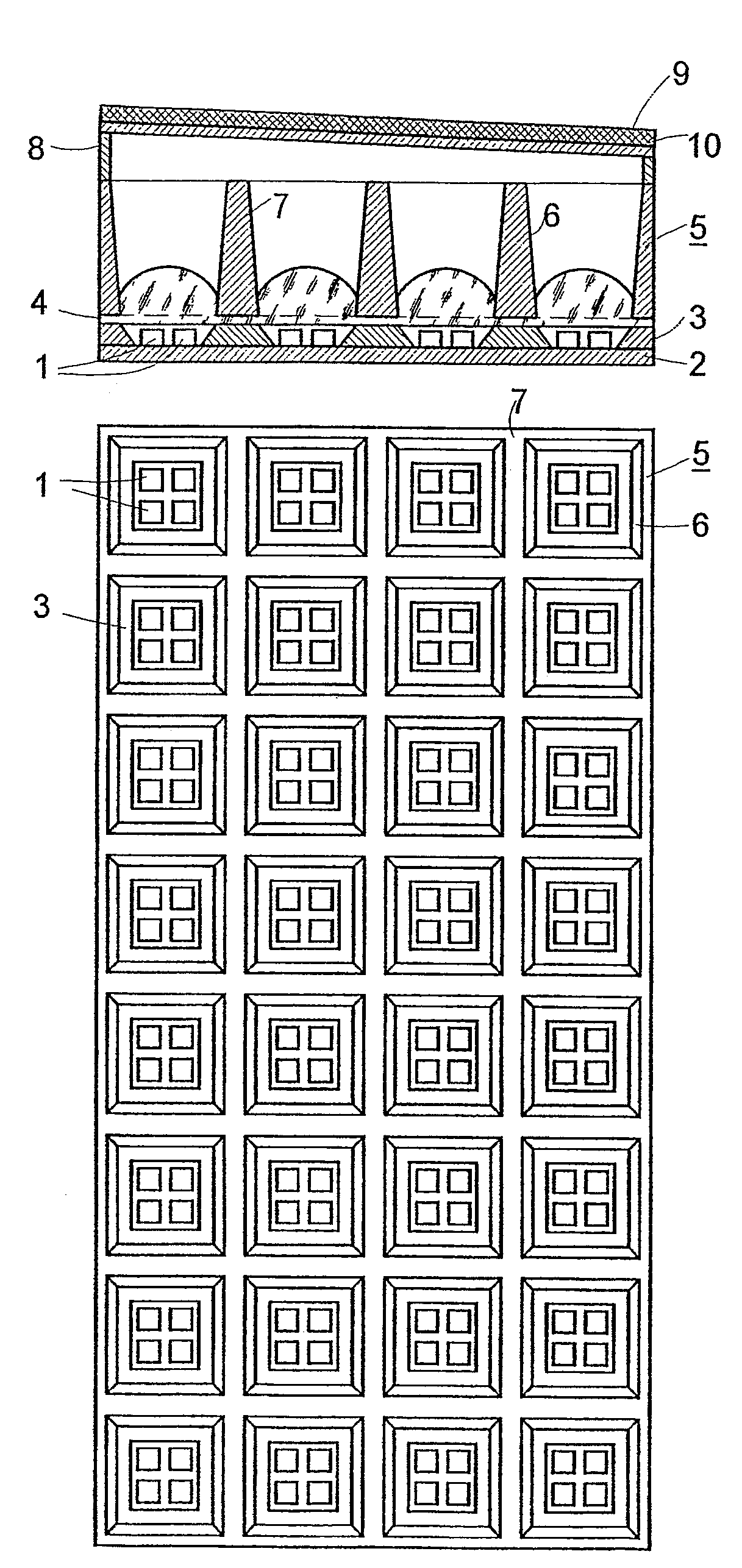
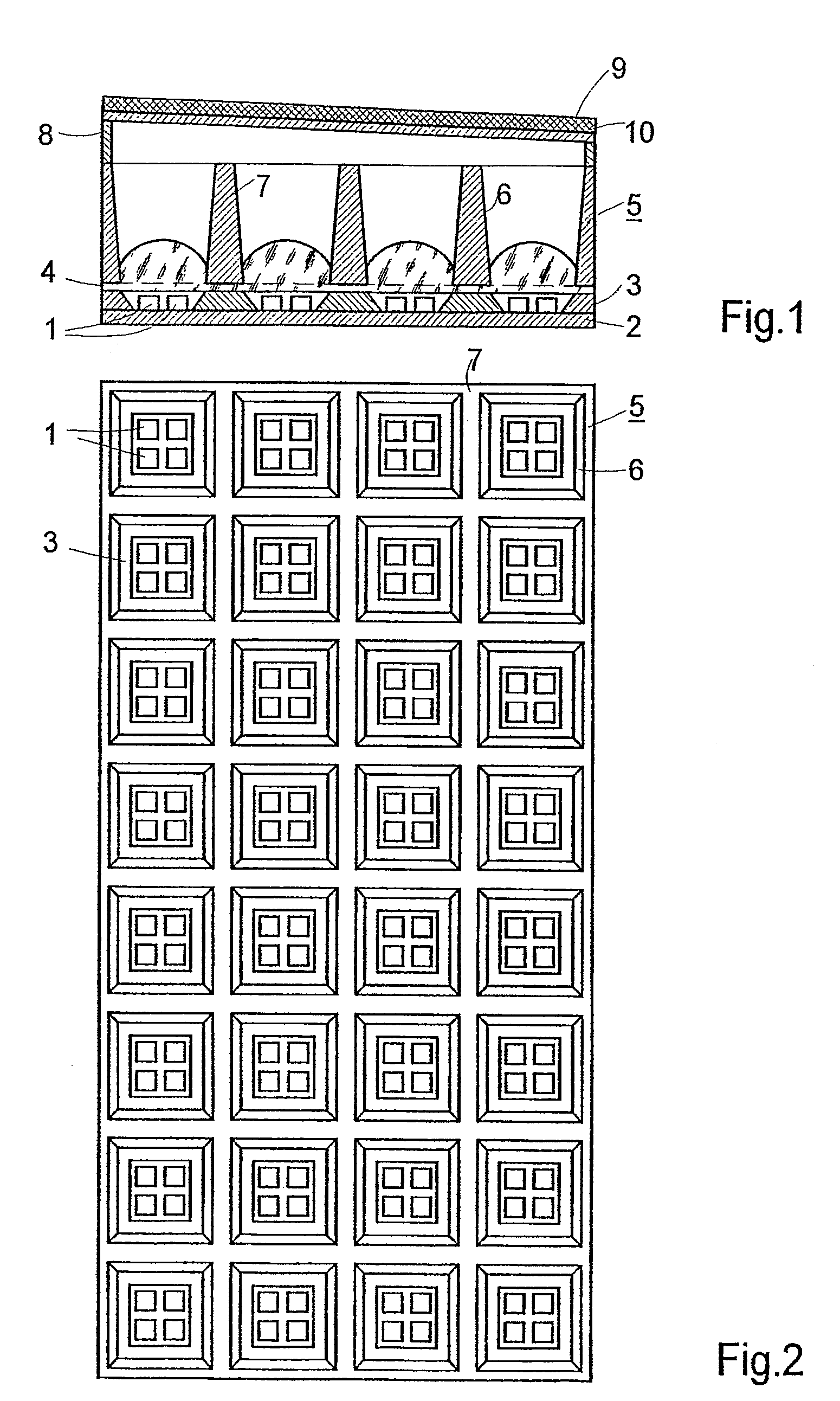
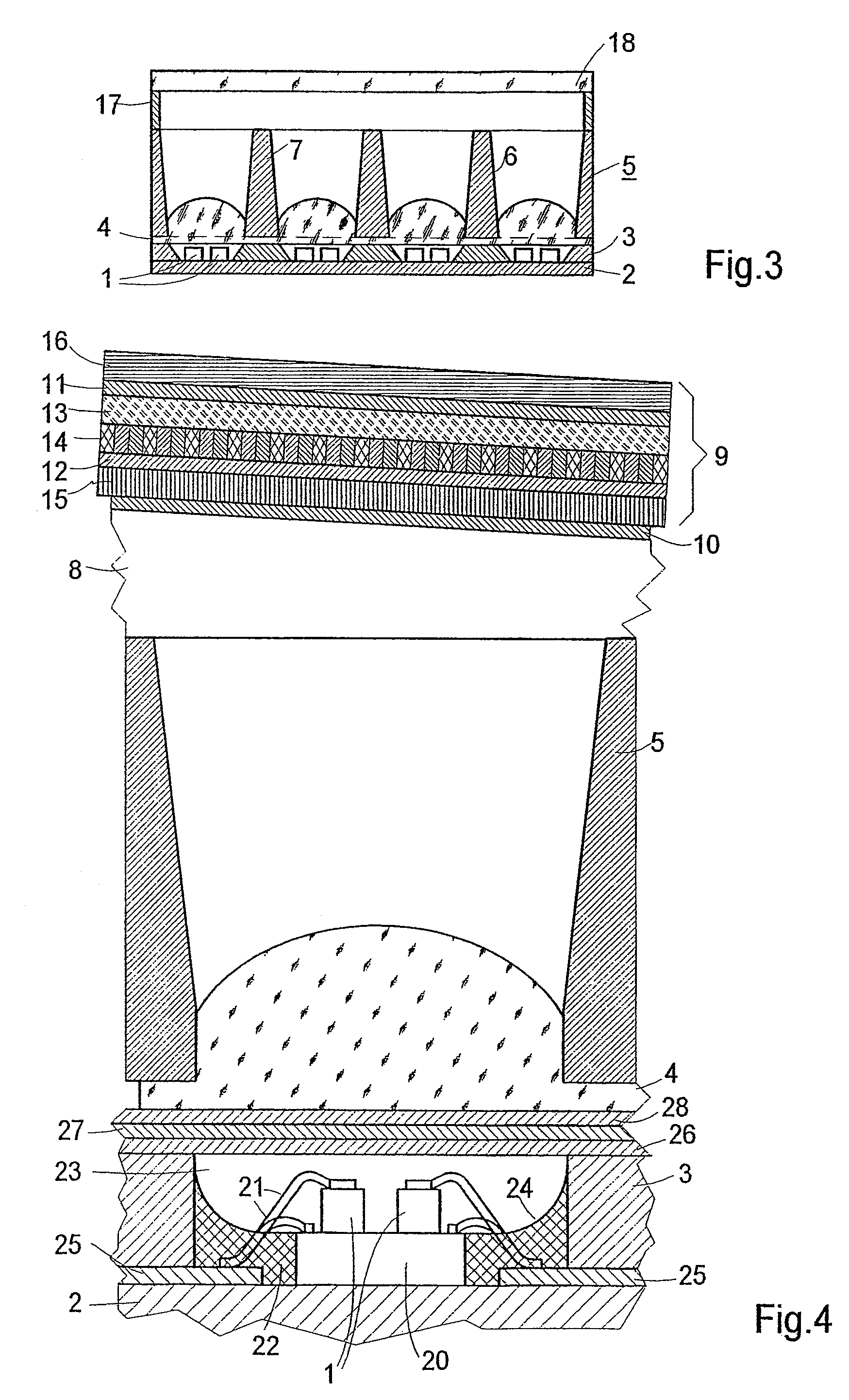
[0022]Provided as light source in the exemplary embodiment according to FIGS. 1 and 2 is a matrix of 4×8 groups of in each case four light emitting diodes 1 that are mounted on a support 2. Webs 3 whose oblique surface serves as reflector are located between the groups.

[0023]A lens array 4 adjoined by a grid reflector 5 lies over the light source 1, 2, 3.

[0024]The webs 3, the lens matrix 4 and the obliquely running surfaces 6 of the grid reflector 5 effect uniform light distribution. In order to avoid shading by the webs 7 of the reflector 5, a frame 8 is provided that effects a spacing between the reflector 5 and the liquid crystal display 9. Located below the liquid crystal display 9 is a diffusing screen 10 which serves the purpose of further improving the uniformity of the backlighting of the liquid crystal display 9.

[0025]The frame 8 positions the liquid crystal display obliquely such that the light incident from above is not reflected in the same direction in which the light a...


PUM


Abstract

A straw holder for supporting a drinking straw in the mouth of a bottle is presented. The holder includes a straw support portion dimensioned for placement across the mouth of a bottle. The straw support portion includes an aperture designed to receive a straw therethrough and to vertically support the straw with respect to the support portion. The holder further includes a bottle retaining portion that includes at least one turn extending around the retaining portion. The at least one turn includes a first turn having an end attached to the straw support portion.

Description

CROSS-REFERENCE TO RELATED APPLICATIONS[0001]This is a U.S. national stage of application No. PCT / DE03 / 02891, filed on 1 Sep. 2003. Priority is claimed on the following application(s): Country: Germany, Application No.: 102 45 933.9, Filed: 30 Sep. 2002 the content of which is / are incorporated herein by reference.BACKGROUND OF THE INVENTION[0002]1. Field of the Invention[0003]The invention relates to a head up display with a device for producing a focused light flux, having a light source and having an image reproduction apparatus including light valves.[0004]2. Description of the Prior Art[0005]In order to convey information to vehicle drivers without the need for them to avert their gaze from the road to be driven or the air space to be flown, so-called head up displays have become known that are used to fade in an image representing information into the windshield of a vehicle. In order for the image still to remain visible in bright ambient light, there is an additional need for...

Claims


Application Information

Patent Timeline
IPC IPC(8): G02B27/14F21V5/00G01D11/28G02B27/10G02B5/02H01L25/075H01L33/60
CPCG02F1/133603H01L25/0753G02F1/133605H01L33/60H01L2224/48472H01L2224/48091H01L2924/00
Inventor BOGNER, GEORGBREINICH, HERBERTLUDEWIG, BERNDMAYER, RALFNOLL, HEINRICHSORG, JORG-ERICH
Owner OSRAM OLED
Learn More