Method and apparatus for rendering three-dimensional object groups

Active Publication Date: 2007-12-18
SONY COMPUTER ENTERTAINMENT INC
View PDF8 Cites 34 Cited by
  • Summary
  • Abstract
  • Description
  • Claims
  • Application Information

AI Technical Summary

Benefits of technology

[0009]The present invention has been made with a view to the above-mentioned problems, and an object thereof is to provide an image processing technology capable of flexibly handling diversified rendering stratagems and to achieve higher efficiency through parallel processing.
[0012]When a plurality of three-dimensional objects are grouped into some groups and the three-dimensional space is divided into the subspaces each of which contains the three-dimensional objects belonging to the same group, the subspaces can overlap one another, however, this kind of overlapping may be allowed. If the space is divided into evenly sized subspaces, the three-dimensional object can be split on the boundary of the subspaces and it becomes difficult to render the object over the boundary. Therefore, by dividing the space into unevenly sized subspaces which contains the three-dimensional objects belonging to the same group allowing overlapping, it becomes possible to adopt rendering stratagem independently by divided subspace unit. For instance, multi-resolution rendering becomes possible in which a resolution which varies by subspace is selected and defocus processing is performed. Furthermore, distributed rendering processing becomes easier since the rendering processing can be performed independently by subspace.
[0017]The rendering processing may be assigned to a plurality of the distributed rendering devices, each of which has different network distance corresponding to level of detail in rendering by subspace unit. For instance, the distributed rendering device at a farther distance from the apparatus on the network may perform the rendering processing for a distant view to be rendered with a coarser level of detail and the communication unit of the apparatus may receive the rendering result from the distributed rendering device with a relatively long latency. On the other hand, the distributed rendering device at a closer distance from the apparatus on the network may perform the rendering processing for a close view to be rendered with a finer level of detail and the communication unit of the apparatus may receive the rendering result from the distributed rendering device with a relatively short latency.

Problems solved by technology

If the space is divided into evenly sized subspaces, the three-dimensional object can be split on the boundary of the subspaces and it becomes difficult to render the object over the boundary.

Method used


Image

  • Method and apparatus for rendering three-dimensional object groups
  • Method and apparatus for rendering three-dimensional object groups
  • Method and apparatus for rendering three-dimensional object groups

Examples


Embodiment Construction

[0059]The invention will now be described by reference to the preferred embodiments. This does not intend to limit the scope of the present invention, but to exemplify the invention.

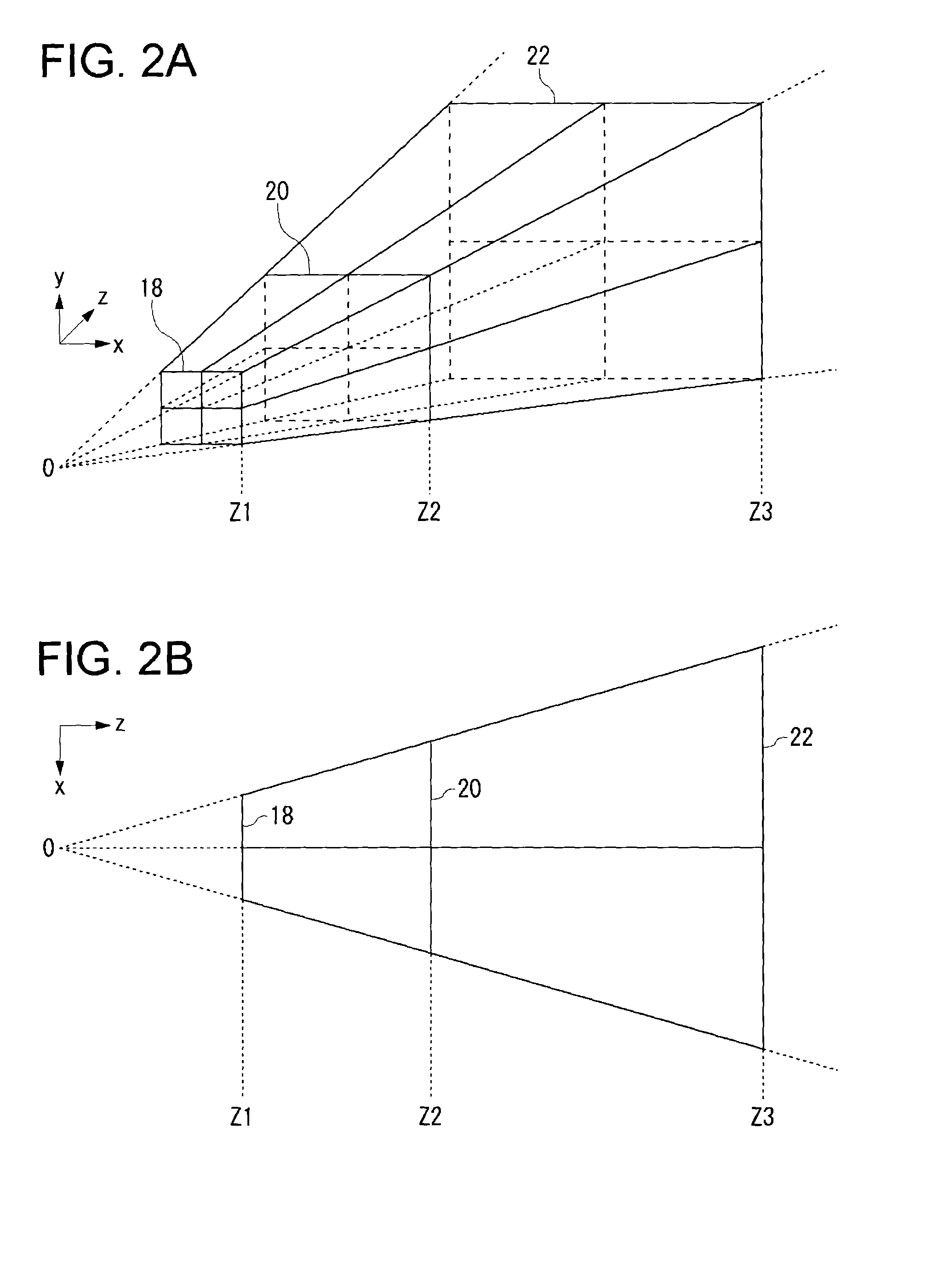
[0060]At the beginning of describing the embodiment of the present invention, its basic concept will be described. A 3-D object is plotted by 3-D world coordinate. In order to render such an object on the screen, it is necessary to designate a view volume in the world coordinate system and according to this view volume, do clipping of the object to be projected on the display screen. As one of the projective methods of displaying a 3-D object on a two-dimensional display, there is a perspective projective method. With the perspective projective method, the apex of a view volume is generally the viewpoint and the view volume is a semi-infinite pyramid defined by the direction and angle from the viewpoint. In the present invention, the object space is divided into subspaces using quadrangular truncated pyr...


PUM


Abstract

An image processing apparatus for performing rendering processing of three-dimensional objects is provided. An object storage unit stores the three-dimensional data of the object and the array data of B-box which encloses the spatial region which the object occupies. A grouping unit reads in the B-box array from the object storage unit, does grouping of multiple B-boxes into groups based on the object characteristics and level of detail information. A rendering processing unit derives a brick in which there are B-boxes belonging to the same group and generates image data by doing rendering processing independently by brick to be stored in an image storage unit. A consolidation unit consolidates the image data per brick stored in the image storage unit and generates the final output image data to be displayed.

Description

BACKGROUND OF THE INVENTION[0001]1. Field of the Invention[0002]The present invention relates to an image processing technology, and it particularly relates to image processing method and apparatus for rendering three-dimensional objects to be displayed on a two-dimensional screen.[0003]2. Description of the Related Art[0004]In applications such as computer games and simulations which use many 3-D graphics, since the viewpoint from which a user views a 3-D object moves and the user moves 3-D objects, high-speed computer graphic (CG) processing is required. To be specific, every time an object or viewpoint moves, it is necessary to do high-speed rendering processing. In this processing the world coordinate of an object is transformed into a two-dimensional coordinate through perspective transformation. Based on this positional information and the texture features of the object surface such as colors and patterns, the color information is determined by pixel unit through rendering pro...

Claims


Application Information

Patent Timeline
IPC IPC(8): G06T15/70G06T15/40G09G5/00G06T15/00
CPCG06T15/20G06T2210/52G06T2210/36G06T13/40G06T17/00
Inventor OHBA, AKIO
Owner SONY COMPUTER ENTERTAINMENT INC
Why Eureka
Try Eureka