
Catheter for delivery of energy to a surgical site

a catheter and surgical technology, applied in the field of percutaneous techniques, can solve the problems of irritating surrounding structures, causing pain and discomfort, and creating fissures, and achieve the effect of reducing the water content of the nucleus pulposus and removing the redundancy of the disc roll

Inactive Publication Date: 2007-12-18
NEUROTHERM
View PDF250 Cites 100 Cited by
  • Summary
  • Abstract
  • Description
  • Claims
  • Application Information

AI Technical Summary

Benefits of technology

Enables non-destructive treatment of degenerative intervertebral discs by denervating nerves, cauterizing granulation tissue, breaking down pain-generating enzyme systems, shrinking collagen, and reducing water content in the nucleus pulposus, thereby alleviating pain and stabilizing the disc without the complications of traditional surgical methods.

Problems solved by technology

Intervertebral disc abnormalities (e.g., morphologic) have a high incidence in the population and may result in pain and discomfort if they impinge on or irritate nerves.
Sneezing, bending or just attrition can tear these degenerated annulus fibers, creating a fissure.
Even if there is no visible extrusion, biochemicals within the disc may still irritate surrounding structures.
Disc fissures can be debilitatingly painful.
Nevertheless, even a contained disc herniation is problematic because the outward protrusion can press on the spinal nerves or irritate other structures.
However, complications include disc space infection, nerve root injury, hematoma formation, instability of the adjacent vertebrae and collapse of the disc from decrease in height.
Another disc problem occurs when the disc bulges outward circumferentially in all directions and not just in one location.
Mechanical stiffness of the joint is reduced and the joint may become unstable.
This problem continues as the body ages, and accounts for shortened stature in old age.
With the increasing life expectancy of the population, such degenerative disc disease and impairment of nerve function are becoming major public health problems.
It has been thought that such disc degeneration creates segmental instability which disturbs sensitive structures which in turn register pain.
However, complications include disc space infection, nerve root injury, hematoma formation, and instability of adjacent vertebrae.
These interventions have been problematic in that alleviation of back pain is unpredictable even if surgery appears successful.
Although pedicle screws provide a high fusion success rate, there is still no direct correlation between fusion success and patient improvement in function and pain.
It is well known to those skilled in the art that percutaneous access to the disc is achieved by placing an introducer into the disc from this posterior lateral approach, but the triangular window does not allow much room to maneuver.
Current methods do not permit percutaneous access to the posterior half of the nucleus or to the posterior wall of the disc.
Major and potentially dangerous surgery is required to access these areas.
In one embodiment the shaft has to be rigid enough to permit the distal end of the RF electrode to pierce the annulus fibrosus, and the ability to maneuver its distal end within the nucleus pulposus is limited.
However, neither embodiment of the devices of the '739 patent permits access to the posterior, posterior lateral and posterior medial region of the disc, nor do they provide for focal delivery of therapy to a selected local region within the disc or precise temperature control at the annulus.
Due to the constrained access from the posterior lateral approach, stiff shaft and lateral energy delivery, the device of the '729 patent is unable to gain close proximity to selected portion(s) of the annulus (i.e., posterior, posterior medial and central posterior) requiring treatment or to precisely control the temperature at the annulus.

Method used


Image

  • Catheter for delivery of energy to a surgical site
  • Catheter for delivery of energy to a surgical site
  • Catheter for delivery of energy to a surgical site

Examples


Embodiment Construction

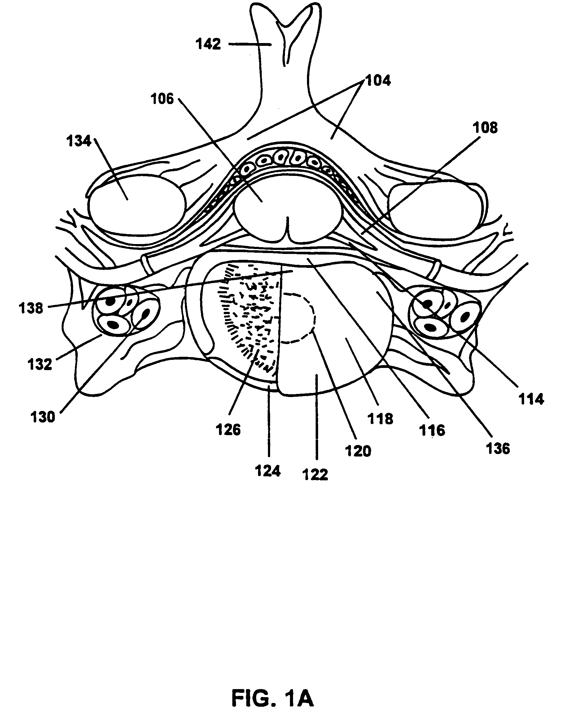
[0059]The present invention provides a method and apparatus for treating intervertebral disc disorders by the application of controlled heating to a localized region of an intervertebral disc. Such disorders include but are not limited to (i) degenerative discs which have tears or fissures in the annulus fibrosis, particularly fissures of the annulus fibrosis, which may or may not be accompanied with contained or escaped extrusions, (ii) contained disc herniations with focal protrusions, and (iii) bulging discs.

[0060]Degenerative discs with tears or fissures are treated non-destructively without the removal of disc tissue other than limited ablation to the nucleus pulposus which changes some of the water content of the nucleus pulposus. Nothing is added to supplement the mechanics of the disc. Electromagnetic energy is delivered to a selected section of the disc in an amount which does not create a destructive lesion to the disc, other than at most a change in the water content of t...


PUM


Abstract

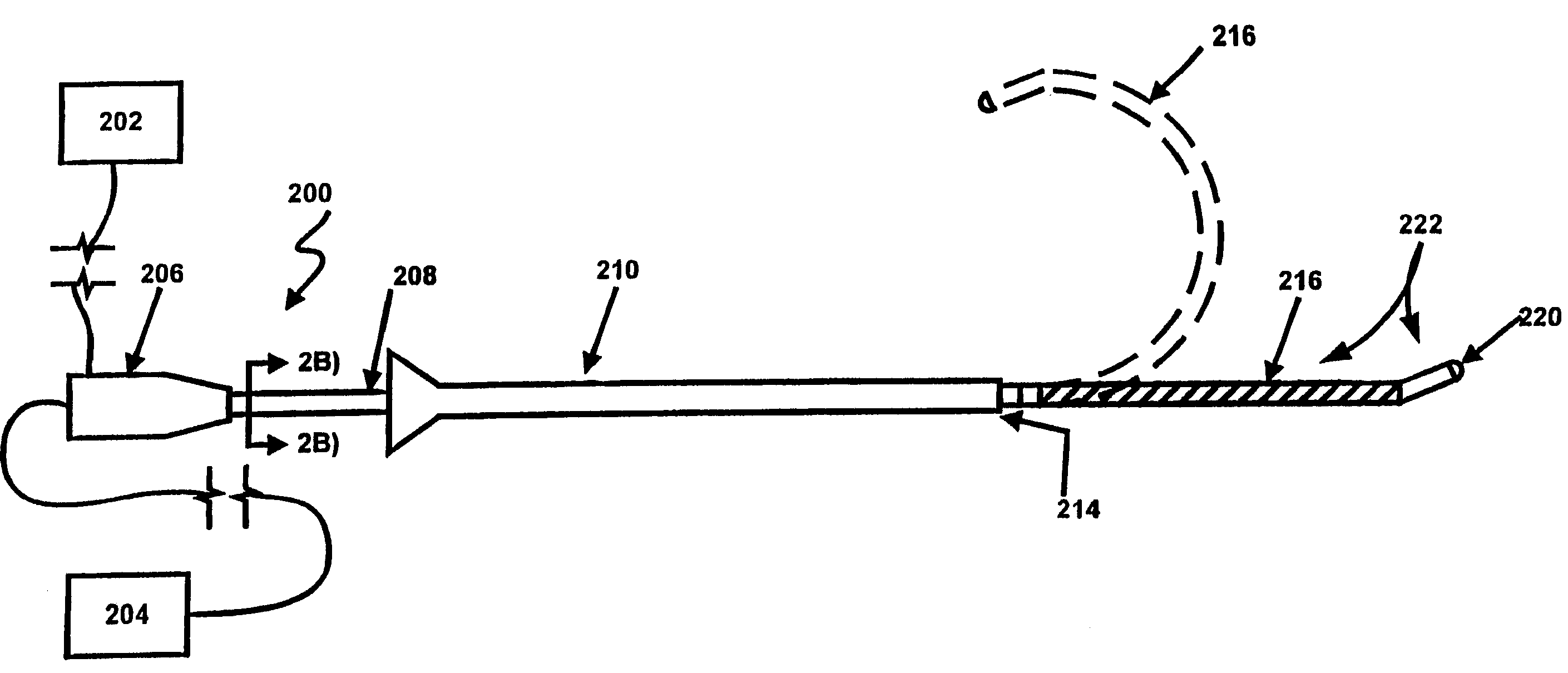
A catheter for delivering energy to a surgical site is disclosed. The catheter includes at a proximal end a handle and at a distal end a probe. The catheter includes at least one energy delivery device and an activation element. The at least one energy delivery device is located at the distal end of the catheter to deliver energy to portions of the surgical site. The activation element is located at the distal end of the catheter, to transition the probe from a linear to a multi-dimensional shape, within the surgical site. Methods for deploying the probe from the linear to multi-dimensional shape are disclosed.In another embodiment of the invention the catheter includes a heating element fabricated on a substrate by photo-etching to deliver thermal energy to portions of the surgical site. In another embodiment of the invention the catheter includes an energy delivery element, a tip and a blade. The energy delivery element is located at the distal end of the catheter to deliver energy to portions of the intervertebral disc. The blade is positioned within a first lumen of the tip and is extensible beyond the tip, to cut selected portions within the intervertebral disc. In another embodiment of the invention a catheter includes both energy and material transfer elements and an interface on the handle thereof. The interface couples the energy delivery element and the material transfer element to external devices for energy and material transfer to and from the intervertebral disc.

Description

REFERENCE TO CO-PENDING APPLICATIONS[0001]This application is a continuation of U.S. patent application Ser. No. 09 / 776,231, filed Feb. 1, 2001, now U.S. Pat. No. 6,767,347, which is a divisional of U.S. patent application Ser. No. 09 / 272,806, filed Mar. 19, 1999, now U.S. Pat. No. 6,258,086, which is a continuation in part of provisional application serial number 60 / 078,545 filed on Mar. 19, 1998. U.S. patent application Ser. No. 09 / 272,806 is also a continuation-in-part of U.S. patent application Ser. Nos. 08 / 881,527, now U.S. Pat. No. 5,980,504, 08 / 881,525, now U.S. Pat. No. 6,122,549, 08 / 881,692, now U.S. Pat. No. 6,073,051, 08 / 881,693, now U.S. Pat. No. 6,007,570, and 08 / 881,694, now U.S. Pat. No. 6,095,149, each of which were filed on Jun. 24, 1997, and each of which claims priority to U.S. Provisional Application Nos. 60 / 047,820, 60 / 047,841, 60 / 047,818, and 60 / 047,848, each of which were filed on May 28, 1997, U.S. Provisional Application No. 60 / 045,941, filed May 8, 1997, an...

Claims


Application Information

Patent Timeline
Patent Type & Authority Patents(United States)
IPC IPC(8): A61B18/18A61B18/12A61B17/00A61B17/16A61B17/22A61B17/28A61B17/32A61B17/34A61B17/88A61B18/00A61B18/04A61B18/08A61B18/14A61B18/24A61B19/00A61F2/30A61F2/44A61F7/02A61M1/00A61M25/00A61M25/01A61M25/09A61N1/06A61N1/30A61N1/40A61N5/04
CPCA61B17/1671A61B17/320016A61B18/00A61B18/082A61B18/148A61B18/1482A61B18/1485A61B18/1492A61N1/06A61N1/40A61B10/02A61B17/00491A61B17/29A61B17/3203A61B17/3421A61B17/3496A61B18/14A61B18/18A61B18/24A61B19/5244A61B2017/00022A61B2017/00084A61B2017/0011A61B2017/00119A61B2017/00261A61B2017/00274A61B2017/003A61B2017/00336A61B2017/00455A61B2017/00867A61B2017/22044A61B2017/22049A61B2017/22082A61B2017/22087A61B2017/2905A61B2017/2927A61B2017/320008A61B2017/320044A61B2017/32113A61B2017/3445A61B2017/3488A61B2018/00011A61B2018/00267A61B2018/00434A61B2018/0044A61B2018/00547A61B2018/00625A61B2018/00654A61B2018/00702A61B2018/00791A61B2018/00797A61B2018/046A61B2018/1266A61B2018/1405A61B2018/1407A61B2018/1412A61B2018/1425A61B2018/1435A61B2018/1455A61B2018/1472A61B2018/1807A61B2019/4054A61B2019/461A61B2019/464A61B2019/5437A61B2217/005A61B2217/007A61B2218/002A61B2218/007A61F2/442A61F2002/30677A61F2007/0298A61M25/0144A61M25/0155A61M25/0158A61M2025/0063A61M2025/0064A61M2025/0163A61B34/20A61B2090/0454A61B2090/061A61B2090/064A61B2090/3937
Inventor ASHLEY, JOHN E.SHARKEY, HUGH R.SAAL, JOELSAAL, JEFFREY A.
Owner NEUROTHERM
Learn More