Eureka AIR delivers breakthrough ideas for toughest innovation challenges, trusted by R&D personnel around the world.

System and method for DC power generation from a reluctance machine

a technology of synchronous reluctance and control system, which is applied in the direction of motor/generator/converter stopper, dynamo-electric converter control, instruments, etc., can solve the problems of significant additional weight of the system, failure of the power generation system system or components, and loss of excitation power to the main machine, so as to reduce the size, weight and cost of the power generation system, and eliminate heat generation.

Inactive Publication Date: 2007-12-11
HONEYWELL INT INC
View PDF11 Cites 7 Cited by
  • Summary
  • Abstract
  • Description
  • Claims
  • Application Information

AI Technical Summary

Benefits of technology

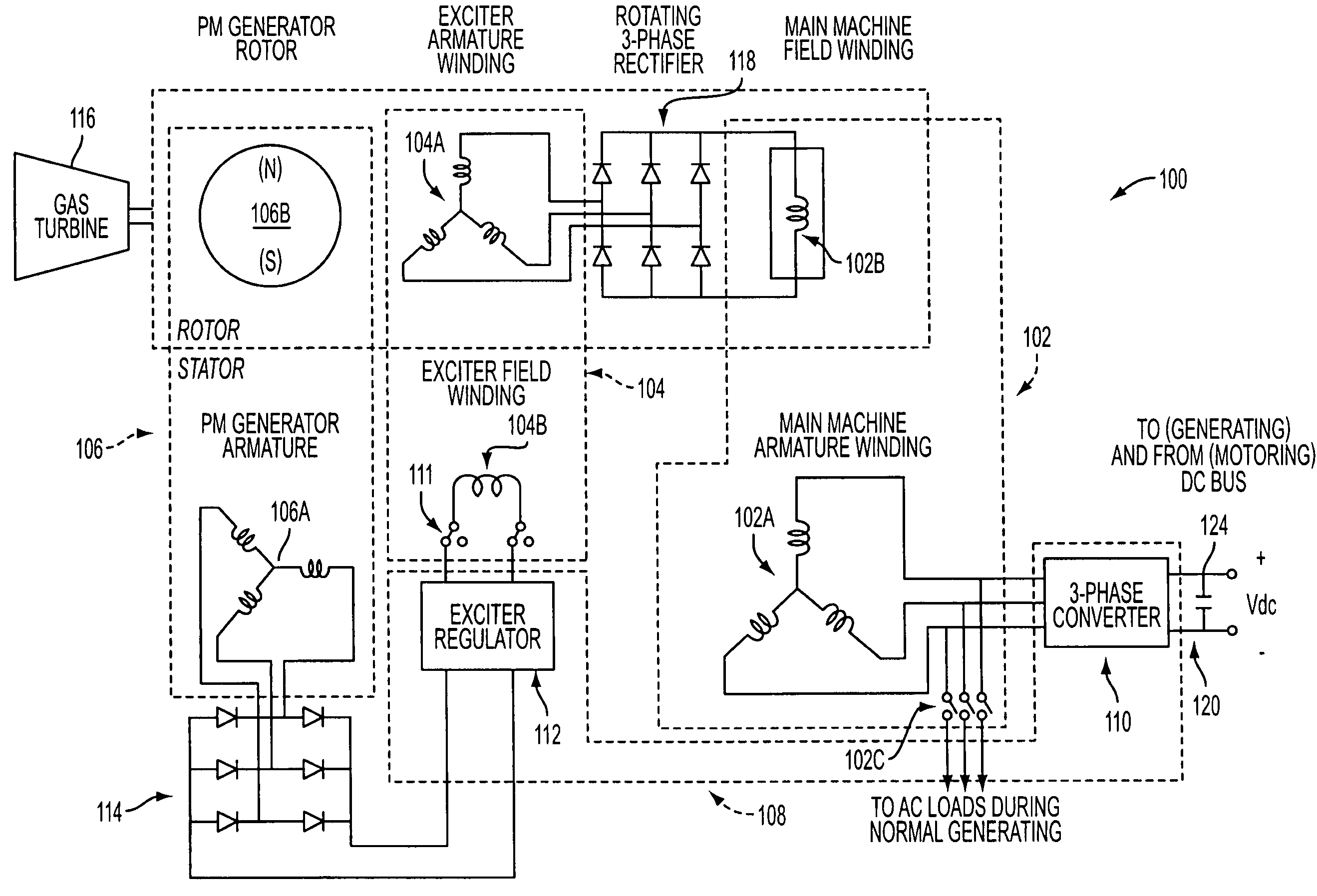
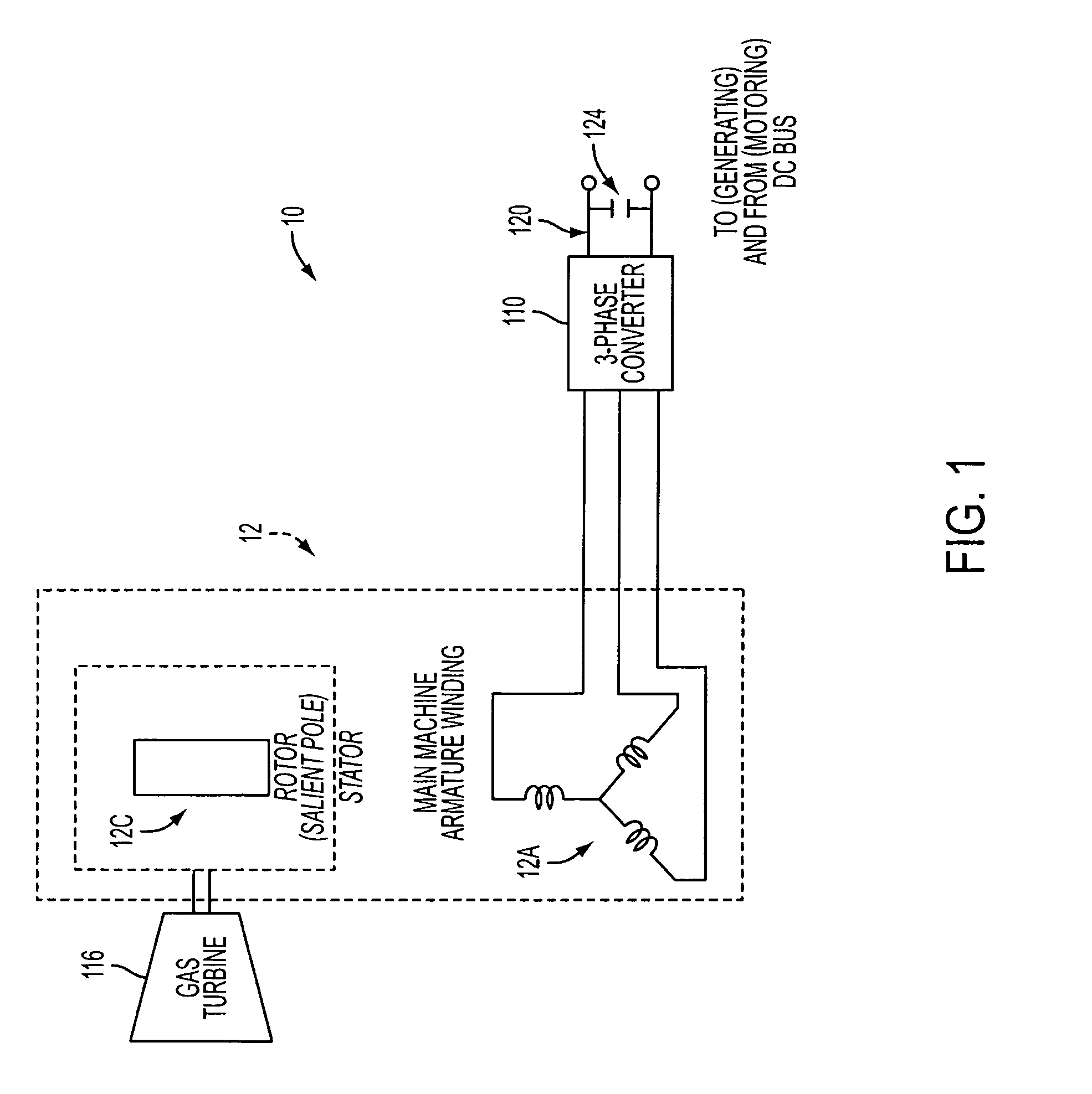
[0010]Another object of exemplary embodiments of the present invention is to provide a power generation control system and method to simplify the traditional generation system by utilizing only a synchronous reluctance machine to eliminate the need for other electrical machines of the traditional aircraft generation system.
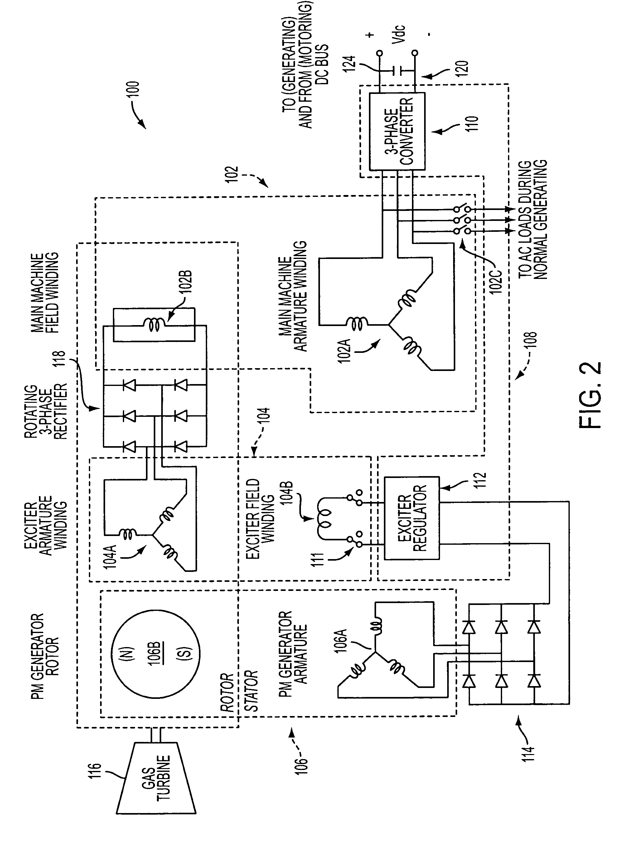
[0013]In accordance with an embodiment of the present invention, a control system and method and a synchronous reluctance machine are gainfully used to achieve DC electric power generation system as well as prime mover startup, such as for a gas engine in an aircraft. Embodiments of the present invention comprise a control system and method for achieving power generation using a synchronous reluctance machine and for providing at least partial power generation using a traditional salient-pole synchronous machine in the case where a loss of excitation of the main machine occurs. Embodiments of the present invention comprise a synchronous reluctance or salient-pole synchronous machine, a power inverter, and associated control electronics to control reluctance power production of the synchronous reluctance machine or degenerated salient-pole synchronous machine. Since embodiments of the present invention operate with no field winding, the need for a PM generator, exciter machine and associated power electronics and control systems for the exciter of the traditional system is eliminated. In doing so, embodiments of the present invention can reduce the size, weight and cost of the power generation system for some applications. A higher mean time between failures value for the overall system can also be achieved. Additional benefits include the elimination of heat generation due to copper losses and conduction losses of rotating diodes in the rotor.
[0014]By utilizing the power generation capability of a synchronous reluctance machine or a resulting synchronous reluctance machine (for example, in the case where a salient-pole synchronous generator has degenerated into a synchronous reluctance machine) where essentially there is no field winding, the need for or dependence upon the permanent magnet generator, exciter machine, exciter power supply and inverter (in the case where prime mover start-up will also be done using only reluctance), the GCU and rotating diode rectifier, can be eliminated. This provides a simple power generation and start up system, as no field excitation of the exciter machine or additional control for field adjustments are required. Embodiments of the present invention can be successfully implemented and provide a lower weight, size and cost, and higher reliability mean time between failures (MTBF) of aircraft power generation systems for a wide range of aircraft, from small to large transport and military aircraft. Additional benefits include a decreased overall space requirement for supporting electronics, as well as the elimination of additional weight and heat generation.

Problems solved by technology

Unfortunately, several such devices may be required in order to ensure sufficient power is available in the event of total engine failure which can incur significant additional weight to the system.
Where engine failure does not occur, of equal concern is the failure of systems or components in the power generation system.
However, the loss of excitation power to the main machine can be caused by the failure of any system or component noted above, including the armature of the PM generator, the diodes of the multiphase rectifier which serve to rectify the output of the armature voltages of the PM generator, the exciter regulator (i.e. semiconductor switches), the generator control unit (GCU), the field and armature of the exciter machine, the diodes of the multiphase rotating rectifier, and the field winding of the machine.
The loss of excitation prevents the production of a main field flux in the main machine, and as a consequence, the machine can not produce any electrical power.

Method used


Image

  • System and method for DC power generation from a reluctance machine
  • System and method for DC power generation from a reluctance machine
  • System and method for DC power generation from a reluctance machine

Examples


Embodiment Construction

[0022]Exemplary embodiments of the present invention comprise a control system and method for achieving power generation using a synchronous reluctance machine or for achieving at least partial power generation using a traditional salient-pole synchronous machine in the case where a loss of excitation of the main machine occurs. Exemplary embodiments of the present invention comprise a synchronous reluctance or salient-pole synchronous machine, a power inverter, and associated control electronics to control reluctance power production of the synchronous reluctance machine or degenerated salient-pole synchronous machine.

[0023]A synchronous reluctance machine can be defined as an electrical machine where there is no field winding or permanent magnet in its rotor, but it has a saliency in its so called d- and q-axis reactances. The stator can be wound with three or more phase sinusoidally distributed windings. In the following exemplary implementations, embodiments of the present inven...


PUM


Abstract

A system and method is provided for generating DC power using a synchronous reluctance machine (12) or a salient-pole synchronous machine (102) and a power converter (110). The present invention can be used to achieve power production for a synchronous reluctance machine (12), or can be used to achieve partial production of power from a traditional salient-pole synchronous machine / starter (102) in the case where the salient-pole synchronous machine / starter has degenerated into a synchronous reluctance machine due to, for example, a loss of excitation. In a power generation system, a control system and method can include a power converter (110), controlled by a voltage command and at least one of a measured DC link (120) voltage or DC link (120) current, for use with a synchronous reluctance machine armature winding (102A) and a prime mover (116), such that movement of the synchronous reluctance machine rotor of the synchronous reluctance machine can be used to produce at least partial DC power generation.

Description

FIELD OF THE INVENTION[0001]The present invention relates to a control system and method for achieving DC power generation from a synchronous reluctance machine. More specifically, the present invention relates to a control system and method to achieve DC power production from a synchronous reluctance machine or partial DC power production from a traditional salient-pole synchronous machine / starter in the case where the salient-pole synchronous machine / starter has degenerated into a reluctance machine.BACKGROUND OF THE INVENTION[0002]Aircraft electrical power systems have increasingly required the development of systems which can provide larger and larger electrical supplies under both normal and abnormal conditions. As noted in U.S. Pat. No. 6,467,725 issued to Coles et al., the entire disclosure of which is incorporated herein by reference, a greater dependence on electrical power requires an electrical supply that is available at all times that an aircraft is in service.[0003]As ...

Claims


Application Information

Patent Timeline
Patent Type & Authority Patents(United States)
IPC IPC(8): H02P3/00
CPCH02P25/08F01D15/10H02P21/12H02P9/302Y02T50/671H02P2101/30F05D2220/7642F05D2220/50Y02T50/60
Inventor SARLIOGLU, BULENTHUGGETT, COLIN E.
Owner HONEYWELL INT INC
Why Eureka
Eureka Blog
Learn More