Method for applying labels

a label and construction technology, applied in the field of label sheet construction, can solve the problems of loss of adhesive tack, poor adhesion to the compact disc in the contaminated area, time-consuming and laborious application of labels, etc., and achieve the effect of facilitating the application of labels

Inactive Publication Date: 2007-12-11
CCL LABEL INC
View PDF56 Cites 27 Cited by
  • Summary
  • Abstract
  • Description
  • Claims
  • Application Information

AI Technical Summary

Benefits of technology

[0008]After the label sheet has passed through a printer or copier and the desired indicia has been printed on the labels, at least one of the tabs is pushed through from the reverse side of the sheet, partially separating the tab from the rest of the sheet. For some label constructions, if there is a second tab, it is preferably pushed through from the reverse side as well. The distance between the tab face cut and the parallel liner cut can be varied in the design to improve functionality, preferably being narrower at the outer extremity, so that the outer edge separates from the rest of the sheet more easily, improving the probability that the perforated edge adjacent to the compact disc label will remain intact. There may or may not be one or more ties in the liner cut near the outer extremity in order to maintain the integrity of the sheet during the manufacturing and printing processes. The tab, which is mostly free of exposed adhesive in that it is still laminated to the die cut section of release liner, is then grasped from the face side, and lifted upward, pulling the compact disc label away from the label sheet. If there is a second tab on the label, this is also removed as the label is removed, and can be grasped by the user's other hand in order to control the position of the label. The user is now able to position the label either directly onto the compact disc or into an alignment apparatus, without any significant contact to an adhesive coated surface. Once the label has been applied to the compact disc, the tabs may be removed by pulling them away from the compact disc, causing the perforation between the tab(s) and the compact disc label to separate.
[0012]According to one definition of the invention, the label sheet is die cut on both the face and liner to facilitate the application of labels onto the dividers and file folders. The label sheet has die cuts that are oriented thereon to allow them to be aligned with either one or more sets of dividers or sets of file folders. The liner is die cut so that a strip can be removed directly from behind the labels, exposing the adhesive side of the labels. The labels are also temporarily held onto the remainder of the sheet by small ties. Removal of the liner from the label sheet allows the user to align the tabs over the substrate using the rest of the label sheet as a carrier. The application of the labels is followed by removal of the label sheet that breaks the ties, leaving just the labels on the substrate. The label applicator construction includes a pressure sensitive laminate material die cut on both the face and liner and sheeted to a standard-size sheet. The facestock of the pressure sensitive laminate material can be either paper or coated film that is toner or ink receptive. The adhesive can be permanent or removable, depending on the level of adhesion needed for the end user.
[0013]A first construction / method of the invention is for applying multiple labels on tab dividers / file folders. The label sheet includes die cuts that are oriented on the sheet in a way that allows them to be aligned with the set of tabs if a set of dividers were stacked on top of each other. The liner is die cut so that a strip, positioned directly behind the labels, can be removed, exposing the adhesive side of the labels. The labels are also temporarily held on the label sheet by small ties. The removal of the liner from the label sheet allows the user to align the tabs over the divider set using the label sheet as a carrier. Once the labels are affixed to the tabs, the user pulls away the label sheet to break the ties, leaving only the labels affixed to the tabs.
[0017]A third construction / method uses multiple sets of tab dividers placed in a device that uses pouches that are tiered. A set of dividers is placed in each of the pouches. The dividers are positioned such that when a label sheet, such as the one described in the first method, is aligned with the top row of tabs, all others will also be aligned. This allows the user to label multiple sets of dividers in a single operation.

Problems solved by technology

Handling of the adhesive side of the label can result in a loss of adhesive tack due to contamination in the area where it was handled, contributing to poor adhesion to the compact disc in the contaminated area.
Application of these labels can be time consuming, clumsy and subject to error, since they must be separated and then attached individually to the corresponding divider tabs.
In the process of individually applying them, they often are not applied evenly or properly with the divider tab sheets.
In other words, the above-described INDEX MAKER product has the problem that the labels are difficult and time consuming to remove from the backing sheet and to place and align on the tabs so they are straight.
They are also small and cumbersome to handle.
This system, while an improvement in certain respects over the prior art, has the disadvantage that the strips are typically flimsy and difficult to properly align.
Additionally, the carrier strip can be sticky and thus may stick to unwanted surfaces.

Method used


Image

  • Method for applying labels
  • Method for applying labels
  • Method for applying labels

Examples


fourth embodiment

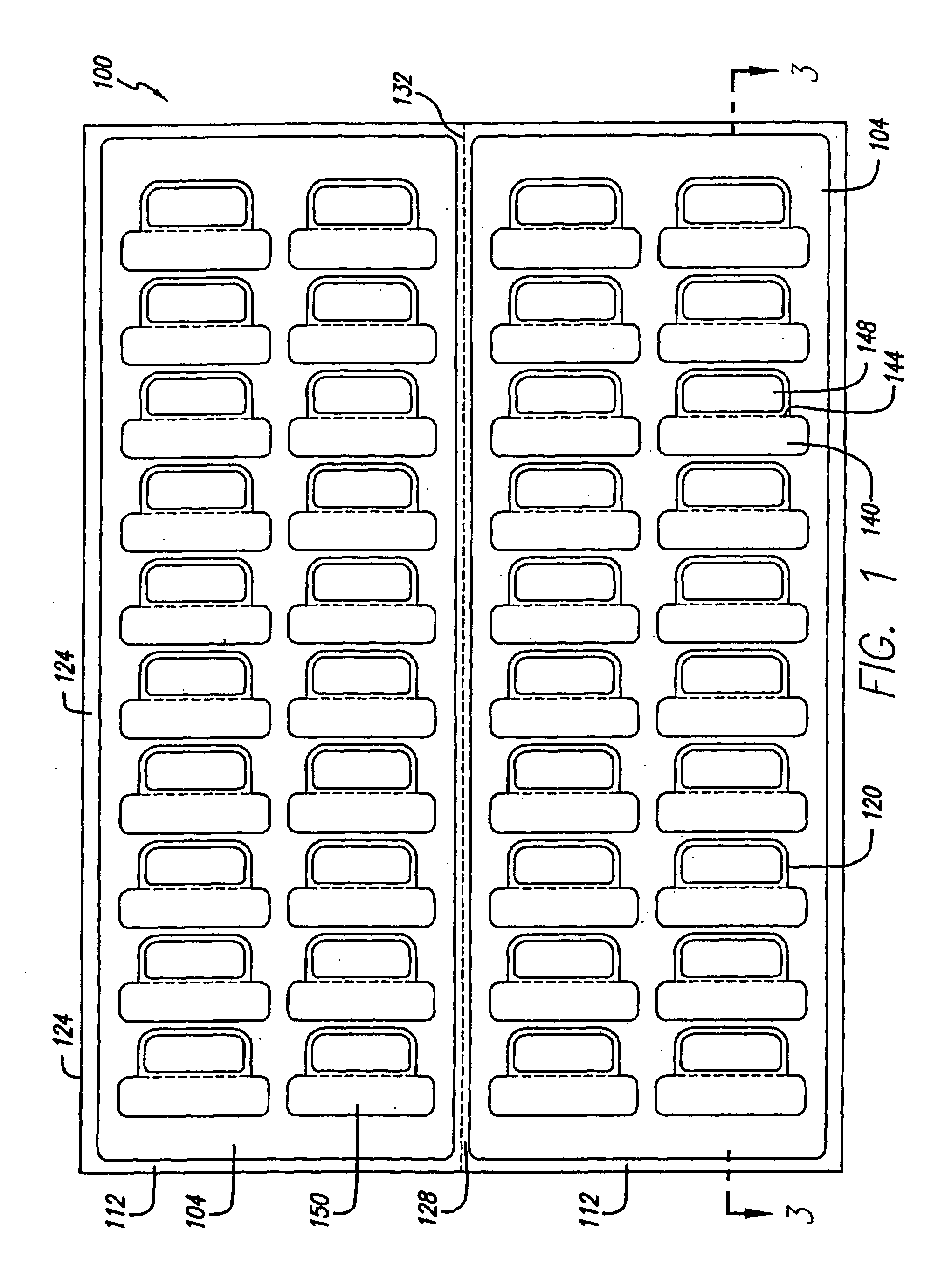
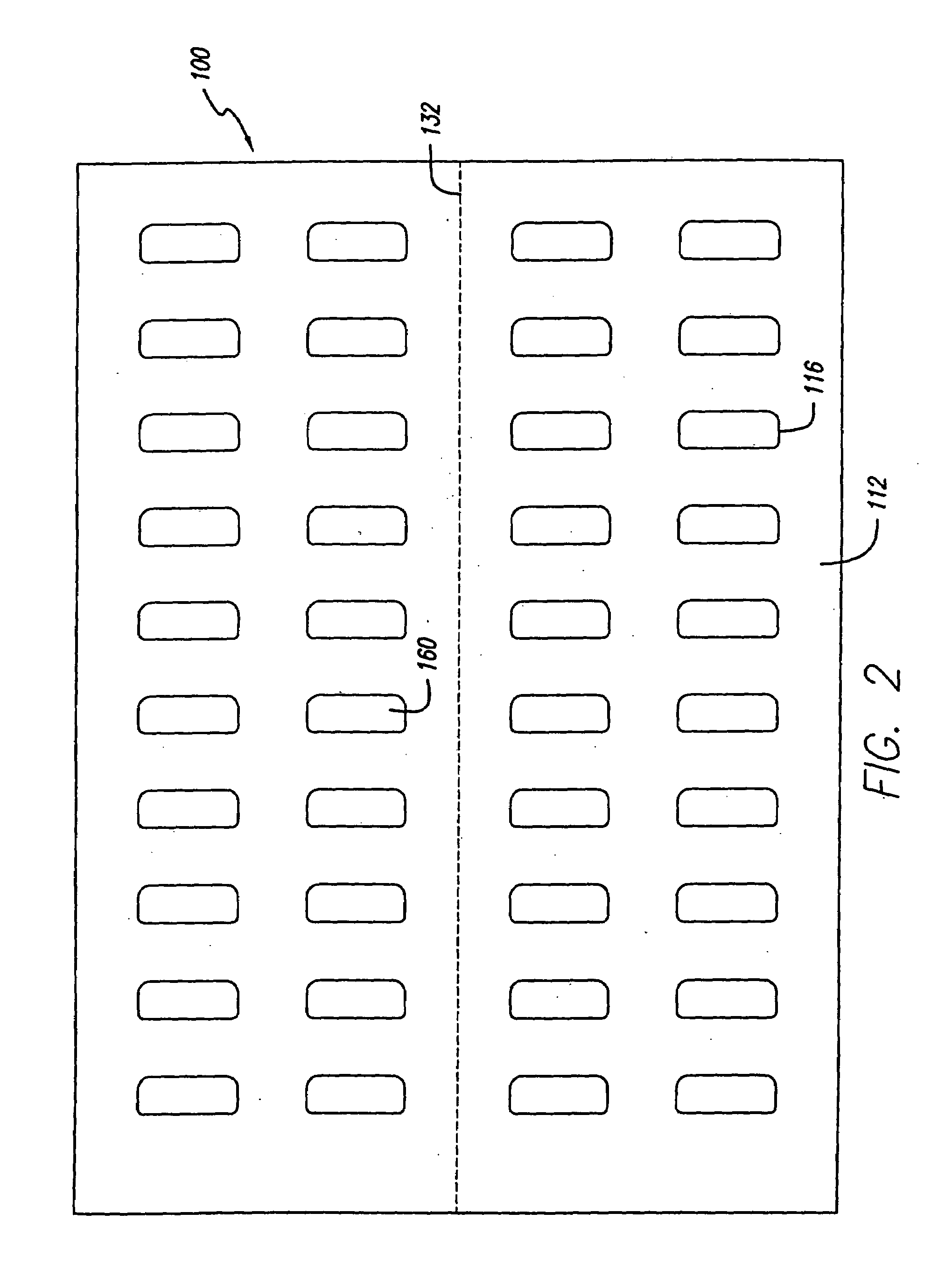
[0087]FIG. 20, shown generally at 400, is an improvement over the embodiment of FIG. 13, and a number of small differences are apparent. It similarly includes facestock 404, liner sheet 408, adhesive, and cut lines to form labels 416, strips, etc. One of the differences is that there is an increased offset between the face and liner cuts. Also, there are more rounded corners, additional ties are provided on the faces, additional ties are provided on the liners and additional rows of labels are provided. The face cuts are provided to relax the post-laser curl in laser printers.

[0088]Referring to FIG. 21, preferred dimensions in inches are: 430a (0.063), 430b (1.251), 430c (R0.125 typical), 430d (0.750), 430e (0.438 typical), 430f (0.219), 430g (0.547), 430h (1.656 typical), 430i (2.031 typical), 430j (0.824 typical (this half of sheet only)), 430k (0.006 first row 0.008 second, third row; 0.010 fourth row tie typical (this half of sheet only)), 430l (0.187 ref.), 430m (0.094 typical)...

embodiment 1400

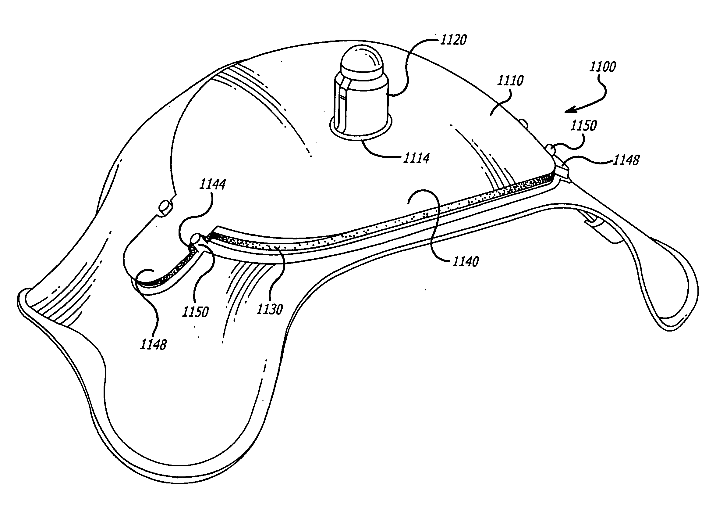
[0116]FIG. 48 shows an alternative sheet embodiment 1400 where the CD label assembly is located symmetrically on the sheet. Tabs 1410 on either side of the label 1420 are formed. The liner section 1420 of the tab is directly underneath the facestock portion 1430 of the tab so that by pushing the liner section, the facestock section partially separates from the sheet. The facestock section 1430 is attached to the compact disc label 1420 by perforations 1440. Lifting the facestock portion of the tab with the attached liner section of the tab lifts the compact disc label 1420 from the liner sheet. The opposed tab with its liner section can be lifted prior to the removal of the compact disc label 1420 or it can be left in and will pull the section of the opposite tab up during removal.

[0117]Referring to FIG. 49, an alternative label sheet embodiment is shown generally at 1500 wherein the alignment tab 1510 which is a perforation cut through both the facestock and the release liner and i...


PUM

PropertyMeasurementUnit
basis weightaaaaaaaaaa
adhesiveaaaaaaaaaa
shapeaaaaaaaaaa

Abstract

A facestock releasably adhered to a liner sheet is die cut to form one or two compact disc labels, and two diametrically opposed tabs on each compact disc label and located so that one edge of the tab is in contact with one of the compact disc labels and is perforated. The liner side of the tab also has a die cut patterned so that it generally follows the outline of the tab, but which forms a shape which is inside of and slightly smaller than the face cut tab pattern. After the label sheet has passed through a printer or copier and the desired indicia has been printed on the labels, at least one of the tabs is pushed through from the reverse side of the sheet, or pulled through via a sheet opening partially separating the tab from the rest of the sheet. The tab, which is mostly free of exposed adhesive in that it is still laminated to the die cut section of release liner, is then grasped from the face side, and lifted upward, pulling the compact disc label away from the label sheet. If there is a second tab on the label, this is also removed as the label is removed, and can be grasped by the user's other hand in order to control the position of the label. The user is now able to position the label either directly onto the compact disc or into an alignment apparatus, without any significant contact to an adhesive coated surface.

Description

CROSS-REFERENCE TO RELATED APPLICATIONS[0001]This is a divisional of copending U.S. patent application Ser. No. 10 / 296,480, filed May 12, 2003, which is a national stage entry of PCT International Application PCT / US01 / 16648, filed May 22, 2001, which claims the benefit of Provisional Application No. 60 / 283,062, filed Apr. 11, 2001, Provisional Application No. 60 / 248,147, filed Nov. 13, 2000, and U.S. patent application Ser. No. 09 / 575,396 filed May 22, 2000, which issued as U.S. Pat. No. 6,803,084 on Oct. 12, 2004. The entire contents of each of these applications are hereby incorporated by reference.BACKGROUND OF THE INVENTION[0002]The present invention relates to label sheet constructions and particularly those having labels designed for application to compact discs. It more particularly relates to such labels that are cut in a facestock sheet that is releasably adhered to a liner sheet to form a label sheet. The label sheet is adapted to be fed into a printer or copier and the de...

Claims


Application Information

Patent Timeline
Patent Type & Authority Patents(United States)
IPC IPC(8): B29C65/00B32B37/00B32B38/18B23K37/04G09F3/10G11B23/40
CPCB65C9/265G09F3/02G09F3/10G11B23/40Y10T428/1495Y10T156/1052Y10T156/1744Y10T428/15Y10T428/14
Inventor HODSDON, JERRY G.TAW, DAISY S.THOMPSON, CHASE TAYLORBANKS, DONALD E.DO, SUNG
Owner CCL LABEL INC
Why Eureka
Try Eureka