
Low-noise vacuum release suction device and controllable aspirator using same

a vacuum release and suction device technology, applied in the field of suction devices, can solve the problems of increased risks discomfort and risks of injury for patients, stress both for patients and medical personnel, and hissing nois

Inactive Publication Date: 2007-12-11
9082 3709 QUEBEC INC KEYVAC R & D
View PDF23 Cites 42 Cited by
  • Summary
  • Abstract
  • Description
  • Claims
  • Application Information

AI Technical Summary

Benefits of technology

"The present invention provides a suction device for an aspirator connectable to a vacuum source. The suction device includes a body with an external surface, an inlet port, an outlet port, and a chamber extending inside the body from the inlet port to the outlet port along a longitudinal axis. The suction device also includes a bypass inlet extending through the body from the external surface in the vicinity of the inlet port to the chamber in the vicinity of the junction position. The bypass inlet is designed to create a flow direction from the inlet port to the chamber that is at an angle with respect to the flow direction from the inlet port to the outlet port. The suction device can generate a first suction force at the inlet port and a second suction force at the bypass inlet, which combine in the chamber near the inner aperture. The technical effect of the invention is to provide a suction device that can efficiently aspirate particles and fluids using a vacuum source."

Problems solved by technology

Firstly, all liquid, solid particles and aerosols must be extracted in an effective manner, due to the health hazards they represent.
The risks for the patient and the medical personnel tend to increase with the increasing use of high technology materials such as polymers and composites yielding toxic resin vapours and microscopic particles of silicium, quartz etc. when shaped with rotary instruments, cut, abraded or polished.
However, contact of the aspirator tip aperture with the tongue or other delicate mouth tissues tends to block airflow, yielding a rapid negative pressure increase firmly grabbing the tissue against the aperture, and causing discomfort and risks of injury for the patient and stress both for the patient and the medical personnel.
Turbulence creates acoustic waves tuned by the resonant cavity provided by the inner chamber, thus generating a hissing noise.
Noise in medical aspirators, particularly dental aspirators used extensively and repeatedly by dentistry personnel, is recognized as a very significant problem.
Indeed, it is a source of fatigue, stress accumulation and it represents a real risk of hearing acuity degradation for medical personnel.
However, the concept of this device provides fixed vacuum compensation and does not allow the user to block one or more of bypass ports 111, 112 to control the aspiration rate at the tip.
Although such a feature is highly desirable in many applications, noise with such a device is still a major problem which prevents its extensive use in applications such as dentistry.
Also, none of the auxiliary aperture shapes have been specifically designed in consideration of the aero-acoustic concerns for optimal merging of the bypass air flow from atmosphere with the main fluid stream, that is with minimal energy being dissipated and converted into sound waves, and minimal transfer of said sound waves to the surrounding work environment.
Although the above examples show that some suction control bypass devices and controlled aspirating devices are contemplated in the prior art, these devices are nevertheless lacking important features necessary for them to provide adequate control of aspiration rate as required in medical applications for instance, while generating low level minimally annoying noise.

Method used


Image

  • Low-noise vacuum release suction device and controllable aspirator using same
  • Low-noise vacuum release suction device and controllable aspirator using same
  • Low-noise vacuum release suction device and controllable aspirator using same

Examples


Embodiment Construction

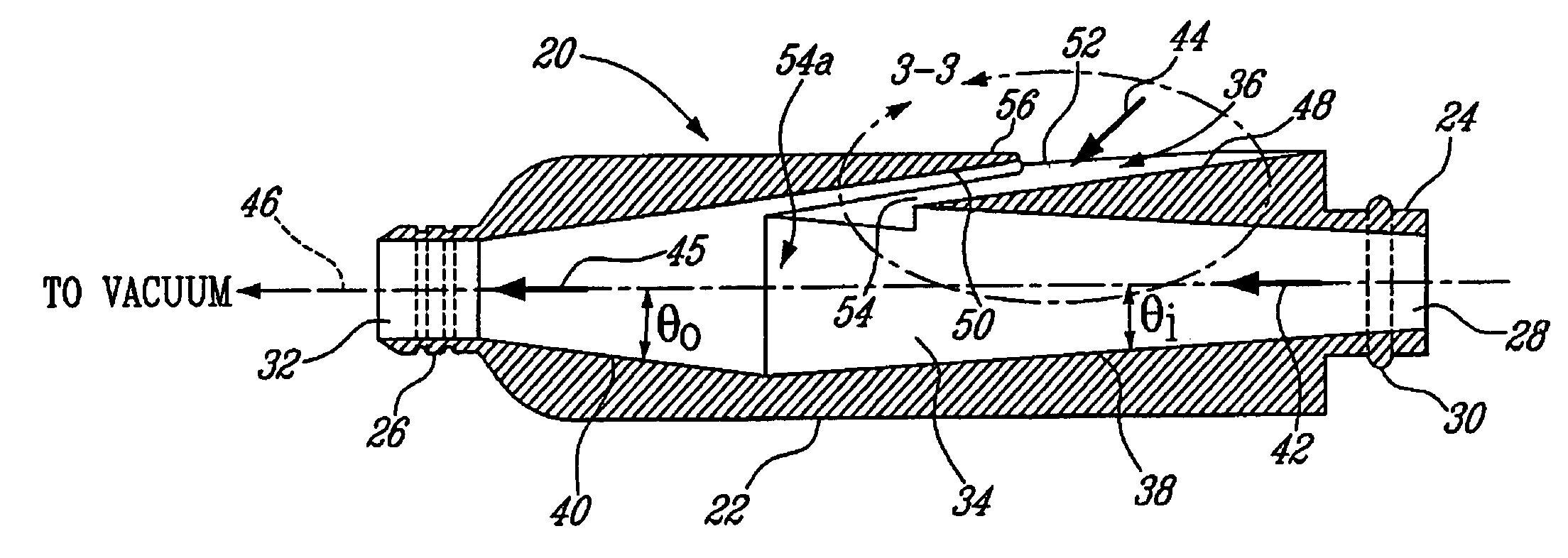
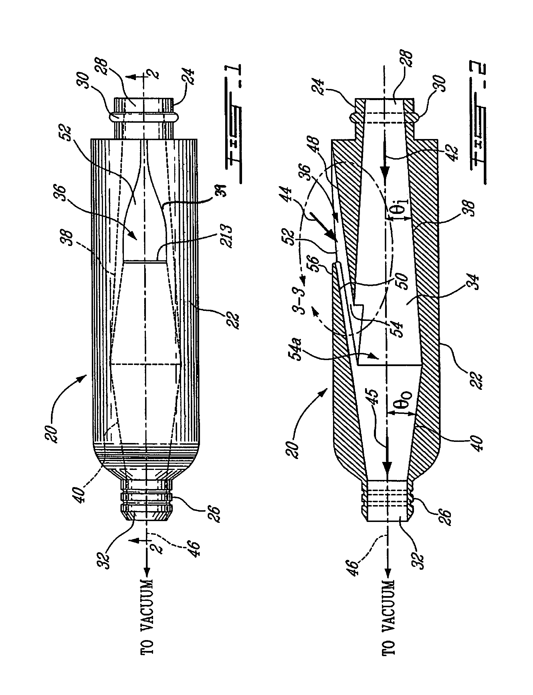
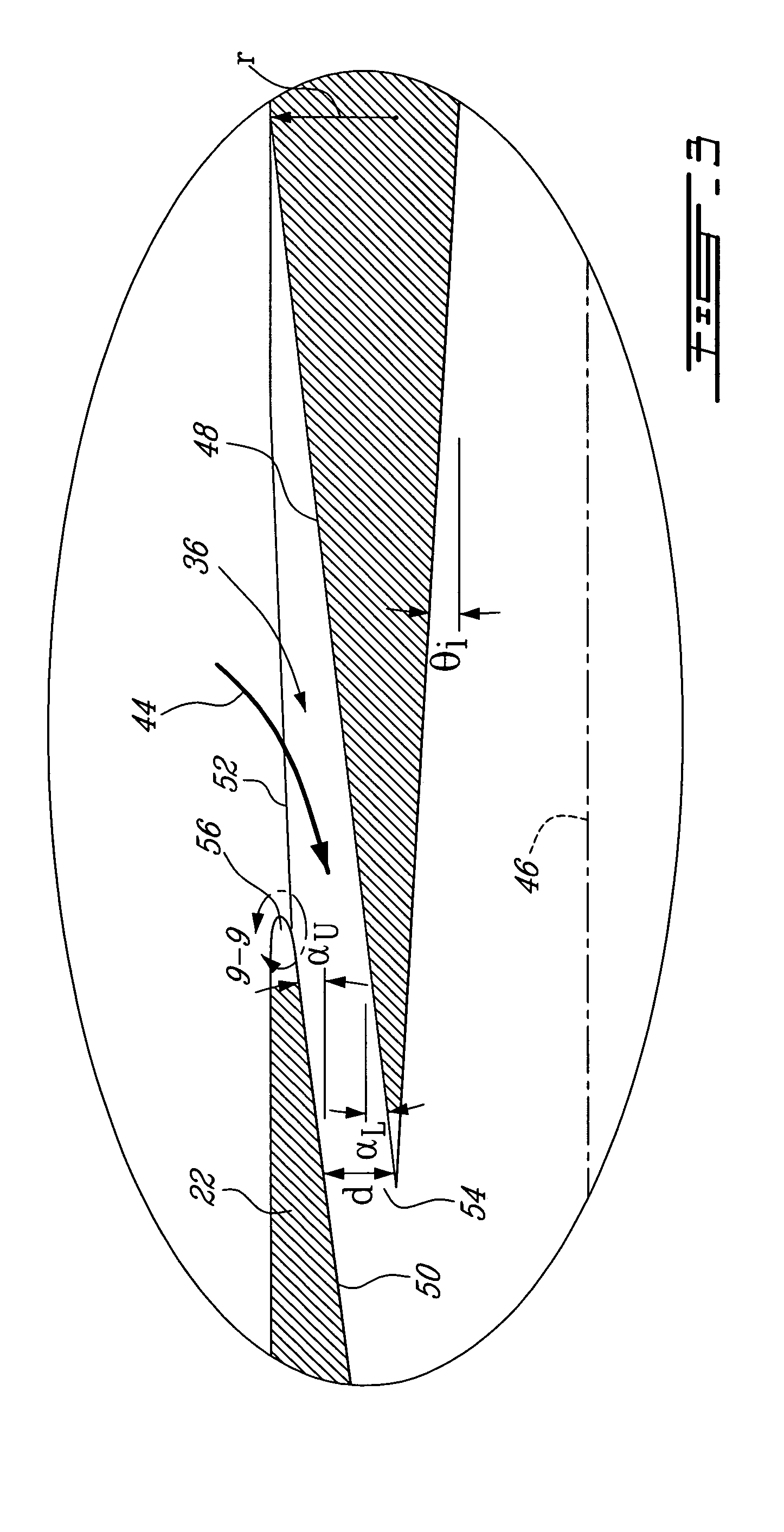
[0040]Generally stated, the present invention relates to a vacuum release or suction device 20, as illustrated in FIGS. 1, 2 and 3, for controlling the suction rate in an aspiration line with minimal generated aerodynamic noise. The invention further relates to a hand-held aspirator of the type used for medical purposes, such as for aspirating body fluids from a patient, saliva, water, blood and debris from a patient's mouth during a dental treatment or surgery, for example. The contemplated aspirator may be controllable and is provided with a low noise suction device 20 of the present invention.

[0041]Examples of prior art aspirators having suction capabilities are illustrated in FIGS. 4 to 6.

[0042]The device 20 according to an embodiment of the present invention will be described.

[0043]The device 20 has a body 22 including a first end or main inlet portion 24 and a second end or main outlet portion 26. The main inlet portion 24 has an inlet port 28 which is so configured as to be m...


PUM


Abstract

The present invention is concerned with a vacuum release suction device for regulating and controlling suction in an aspiration line, and which may be included in aspirators such as for example dentistry, surgery, or cosmetic tools. When operated, such tools generally generate noise which may become harmful to the tool user or for the patient on which the tool is used. More specifically, the suction device of the present invention includes a body having an inlet port and an outlet port defining a chamber in the body and a bypass inlet intersecting the chamber at an acute angle with respect to the longitudinal axis of the chamber, such that a main fluid stream is generated with minimized occurrences of flow separation, turbulence and therefore minimized generated aerodynamic noise.

Description

FIELD OF THE INVENTION[0001]The present invention generally relates to a suction device. More specifically, the present invention is concerned with a low noise vacuum release suction device and controllable aspirator using same.BACKGROUND OF THE INVENTION[0002]Aspirators connecting a vacuum source to a nozzle having a hollow tip are widely used in a plurality of professional fields and, namely, in the medical field. In dentistry, for instance, aspirators are used by dentists or hygienists and dental assistants for aspirating saliva, blood, water and debris from the patient's mouth during a treatment or surgery. The aspirating tool and the user thereof have to deal with opposite concerns in such an application.[0003]Firstly, all liquid, solid particles and aerosols must be extracted in an effective manner, due to the health hazards they represent. The risks for the patient and the medical personnel tend to increase with the increasing use of high technology materials such as polymers...

Claims


Application Information

Patent Timeline
Patent Type & Authority Patents(United States)
IPC IPC(8): A61M1/00A61C17/08
CPCA61C17/043A61M1/0047A61M2206/11A61M2205/42A61C17/13A61M1/7411A61C17/08
Inventor LEMOINE, PATRICK D.BOLDUC, MAXIMEBROUILLETTE, MARTINPLANTE, JEAN-SEBASTIEN
Owner 9082 3709 QUEBEC INC KEYVAC R & D
Learn More