
Heart treatment equipment for treating heart failure

a heart failure and heart pumping technology, applied in the field of heart treatment equipment for treating a heart failure, can solve the problems of cardiac output decline, cardiac conduction disturbance, heart pumping dysfunction, etc., and achieve the effect of reducing the electric power consumption and the operation rate of stimulation

Inactive Publication Date: 2007-12-04
TERUMO KK
View PDF12 Cites 72 Cited by
  • Summary
  • Abstract
  • Description
  • Claims
  • Application Information

AI Technical Summary

Benefits of technology

[0015]Additionally, another purpose of the present invention is to propose a heart treatment equipment for treating a heart failure where the ventricle stimulation is controlled in accordance with the heart failure symptoms and the electric power consumption is reduced by lowering the operation rate of the stimulation for both the ventricles.
[0019]In these heart treatment equipments of exemplified embodiments where a stimulation of a vagus nerve and stimulations of both ventricles are carried out in cooperation, it becomes possible to inhibit the lowering of the cardiac output based on the stimulation of the vagus and at the same time it becomes possible to stimulate the ventricle for each of heart failure patients at an optimum timing after the spontaneous contraction of the atrium.
[0022]According to the heart treatment equipment of the present invention, either one of the ventricle stimulation modes of both ventricle stimulation and single ventricle stimulation is selected in accordance with the heart rate, so that the operation rate of the stimulation for both the ventricles is lowered and it is possible to reduce the electric power consumption.

Problems solved by technology

The electric stimulation of the vagus nerve also made distribution of the cardiac conduction velocity non-uniform in the ventricle in connection with the region and the seriousness about the myocardial injury and / or disease of the organic heart disease, so that there was a problem of causing a cardiac conduction disturbance.
For example, when a phenomenon where a cardiac conduction system cannot conduct a impulse to the right ventricle or the left ventricle or a phenomenon where a conduction of a impulse is delayed occurs, the efficient blood ejection based on a harmonic contraction of the right ventricle and left ventricle cannot be achieved, so that the heart pumping dysfunction develops.
As a result, the cardiac output decreases and an organic heart disease patient whose cardiac function is lowered decreased would have a further deterioration of cardiac function and develops a heart failure.
Similarly, the decreasing of a ventricle contraction force caused by a negative inotropic effect would develop a heart failure.
In case when the pump function of the ventricle cannot follow this increase of a heart rate, the increase of the cardiac output cannot be expected and what is even worse, the cardiac output may decrease oppositely.
Therefore, there was a problem that the rapid increase in a heart rate occurs for a heart failure patient even in minimal exertion and he cannot continue exertion such that he feels palpitation, fatigue and the like owing to a fact that the pump function of the ventricle cannot follow this increase of a heart rate.
Additionally, it is difficult for the left ventricle stimulation to fix the electrode at an aimed region of the coronary sinus and there is a possibility of transferring the electrode after fixed, so that a large margin is set for the stimulation voltage relative to the stimulation threshold in order to surely carry out the stimulation.
As a result, the electric power consumption of the left ventricle stimulation increases very much, so that the electric power consumption for the stimulation of both the ventricles where the right ventricle and the left ventricle are stimulated at the same time becomes much bigger.
Consequently, there was a problem of shortening the battery life caused by its electric power consumption if the stimulation is always carried out for the left ventricle or for both the ventricles.

Method used


Image

  • Heart treatment equipment for treating heart failure
  • Heart treatment equipment for treating heart failure
  • Heart treatment equipment for treating heart failure

Examples


Embodiment Construction

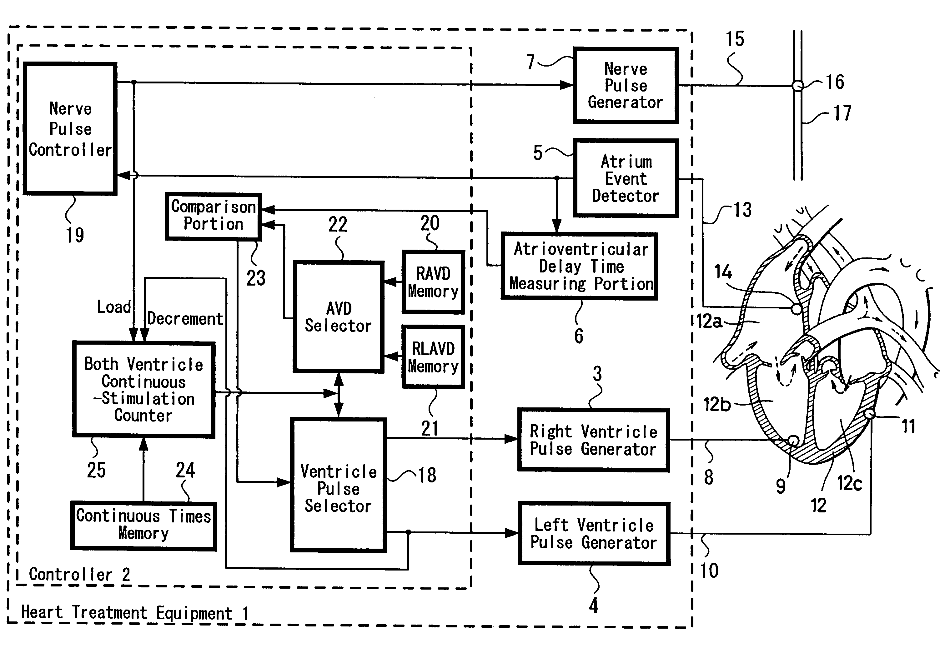
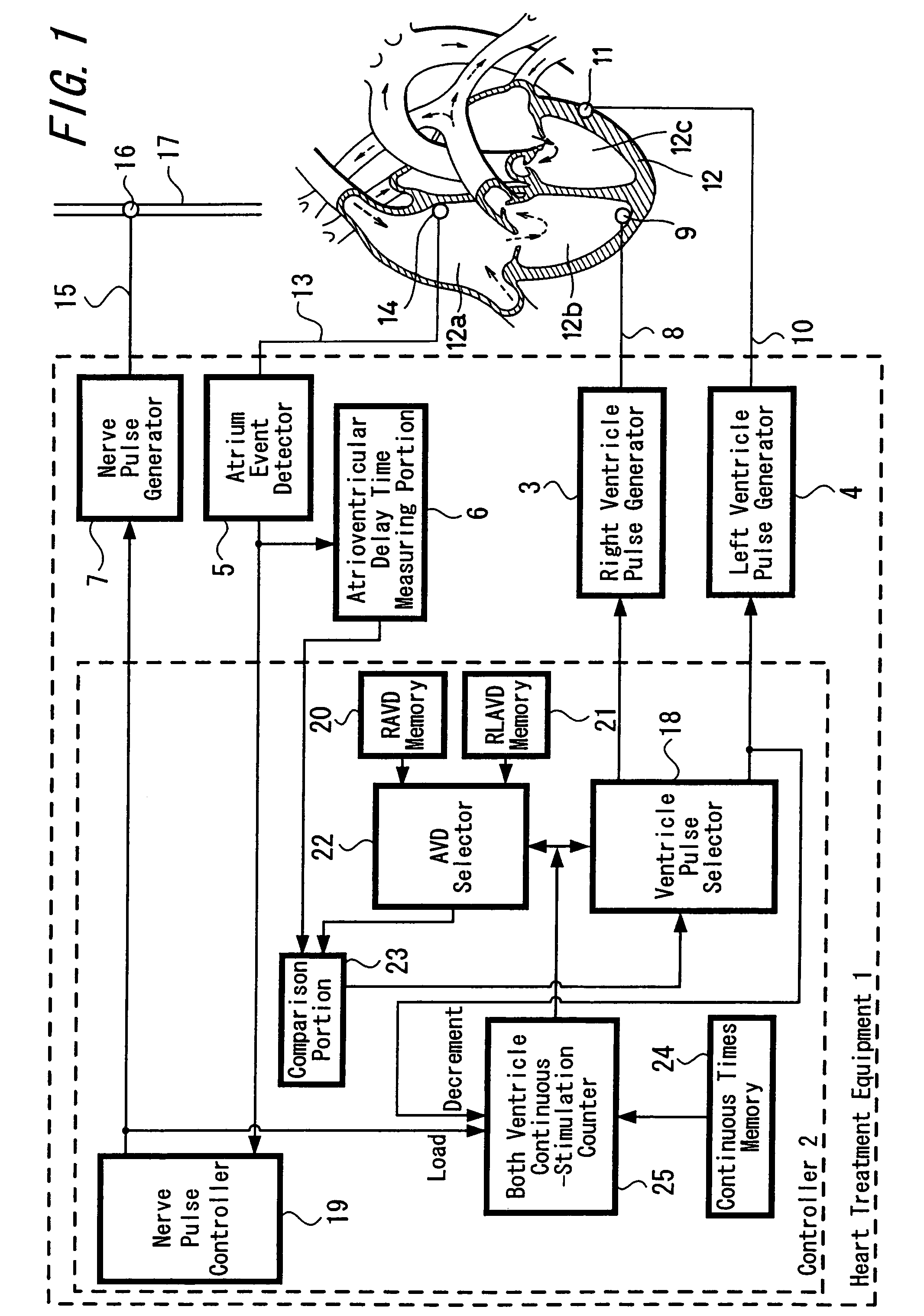
[0034]A first exemplified embodiment of a heart treatment equipment according to the present invention will be precisely described in connection with FIG. 1. It should be noted that the term “event” of a heart in this specification includes any contraction phenomenon which arose in the heart (atrium and / or ventricle) regardless of a cause by stimulation and of a spontaneous cause.

[0035]A heart treatment equipment 1 is constituted by a controller 2, a right ventricle pulse generator 3 which generates a right ventricle stimulation pulse for stimulating the right ventricle of the heart, a left ventricle pulse generator 4 which generates a left ventricle stimulation pulse for stimulating the left ventricle of the heart, an atrium event detector 5 for detecting an atrium contraction of the heart (atrium event), an atrioventricular delay time measuring portion 6 responsive to the atrium event for measuring a predetermined time until when a ventricle stimulation pulse which stimulates the ...


PUM


Abstract

In a heart treatment equipment provided with a stimulating mechanism for both the ventricles, the both ventricle stimulation is made optimized in order to inhibit the decrease of the cardiac output when a heart rate increase or the vagus nerve stimulation is performed and the equipment comprises a right ventricle pulse generator for stimulation the right ventricle, a left ventricle pulse generator for stimulation the left ventricle, wherein the controller for selecting either one of aforesaid right ventricle pulse generator and left ventricle pulse generator or selecting both of them for the ventricle stimulation is constituted such as to select both of the right ventricle pulse generator and the left ventricle pulse generator in response to the vagus nerve stimulation or the heart rate monitor output.

Description

BACKGROUND OF THE INVENTION[0001]1. Field of the Invention[0002]The present invention relates to a heart treatment equipment for treating a heart failure and more particularly to a heart treatment equipment where a heart failure is treated in such a way that right and left ventricles are stimulated at the same time in response to the stimulation of the vagus nerve or the heart rate increase.[0003]2. Description of the Related Art[0004]A cardiac activity is put under the antagonistic control of an automatic nervous system and the automatic nervous system has a sympathetic nerve and a parasympathetic nerve where the parasympathetic nerve of the heart is a vagus nerve and the increase in the sympathetic tone has an excitatory effect on the cardiac activity and the increase in the vagal tone has an inhibitory effect on the cardiac activity.[0005]The inhibitory effect on cardiac activity by the increase of the vagal tone mainly causes a decrease of the heart rate and the arterial blood p...

Claims


Application Information

Patent Timeline
Patent Type & Authority Patents(United States)
IPC IPC(8): A61N1/368A61N1/36A61N1/362
CPCA61N1/36114A61N1/3627A61N1/3684A61N1/36843
Inventor FUKUI, YOSHIHITO
Owner TERUMO KK
Learn More