
Method and apparatus for continuously feeding and pressurizing a solid material into a high pressure system

a high-pressure system and solid material technology, applied in conveyors, combustible gas production, lighting and heating apparatus, etc., can solve the problems of reducing the efficiency of the reactor, difficult to pressurize to the high pressure needed for combustion, and many inefficiencies in the system, so as to eliminate the reverse movement of the material

Active Publication Date: 2007-12-04
THE BOEING CO +1
View PDF18 Cites 54 Cited by
  • Summary
  • Abstract
  • Description
  • Claims
  • Application Information

AI Technical Summary

Benefits of technology

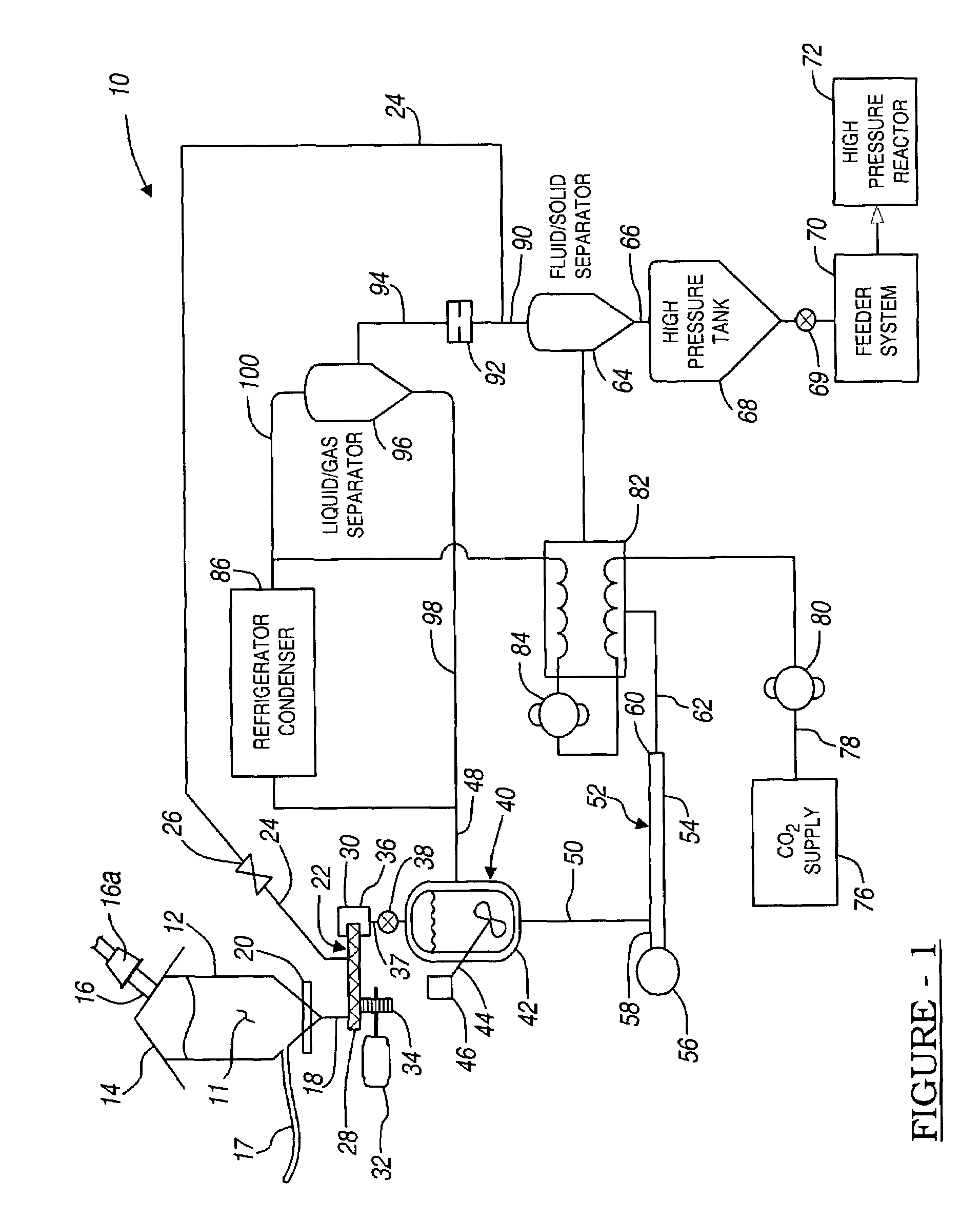
[0011]A third preferred embodiment of the present invention provides a system to substantially continuously provide a pressurized coal slurry to a pressurized holding tank. The system has a receptacle to supply the coal at an ambient pressure to a receptacle outlet. Also included is a feeder that has a feeder inlet operably connected with the receptacle outlet such that a portion of the coal is adapted to be selectively and continuously supplied to the feeder. A slurry tank holds a slurry of the coal and a liquid at a pressure at least twice as great as the ambient pressure of the container. The tank also has a tank inlet operably connected to a feeder outlet. A slurry pump pumps the slurry from the slurry tank to a high pressure tank. The slurry pump increases the pressure of the slurry by at least four times.
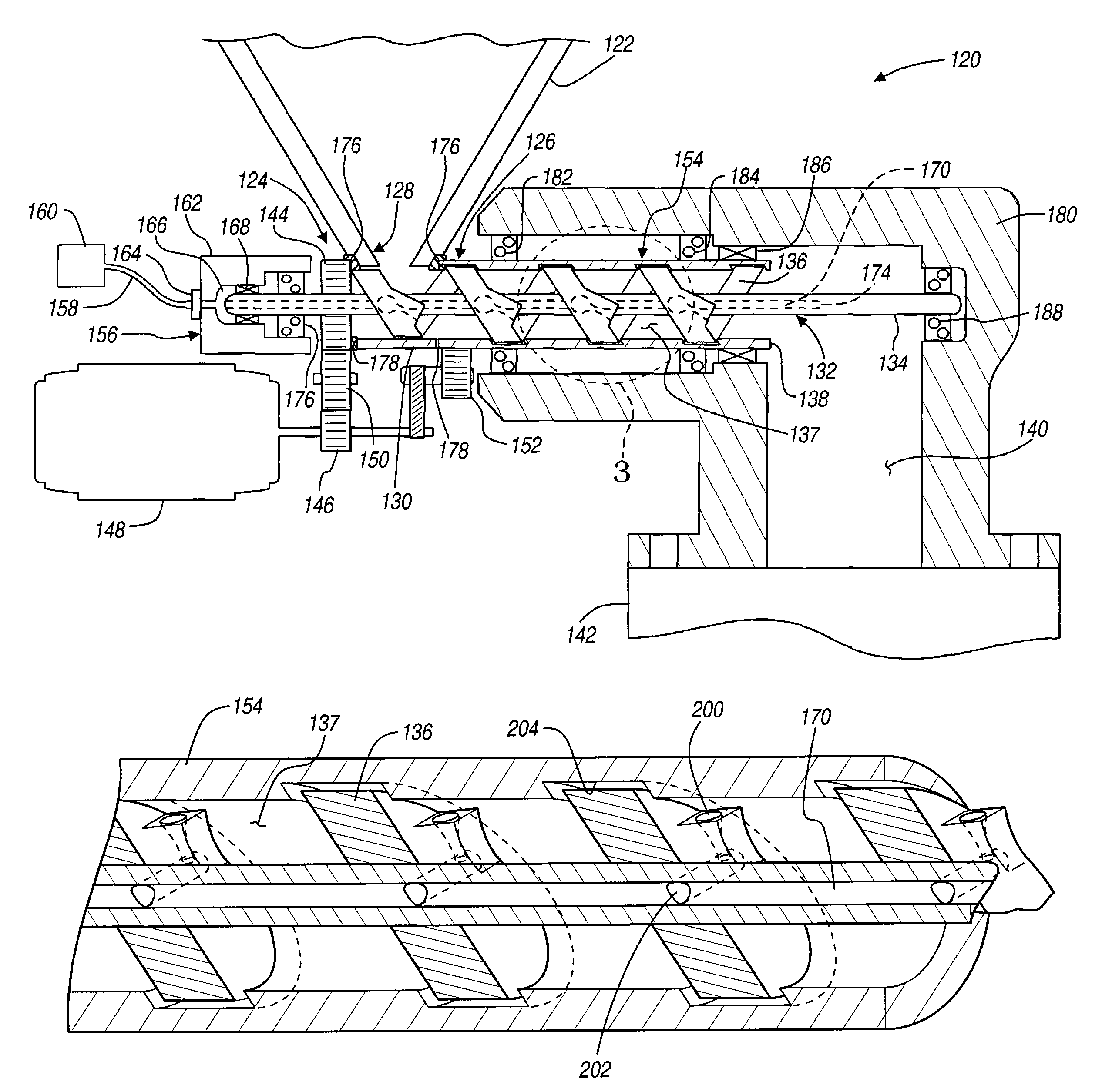
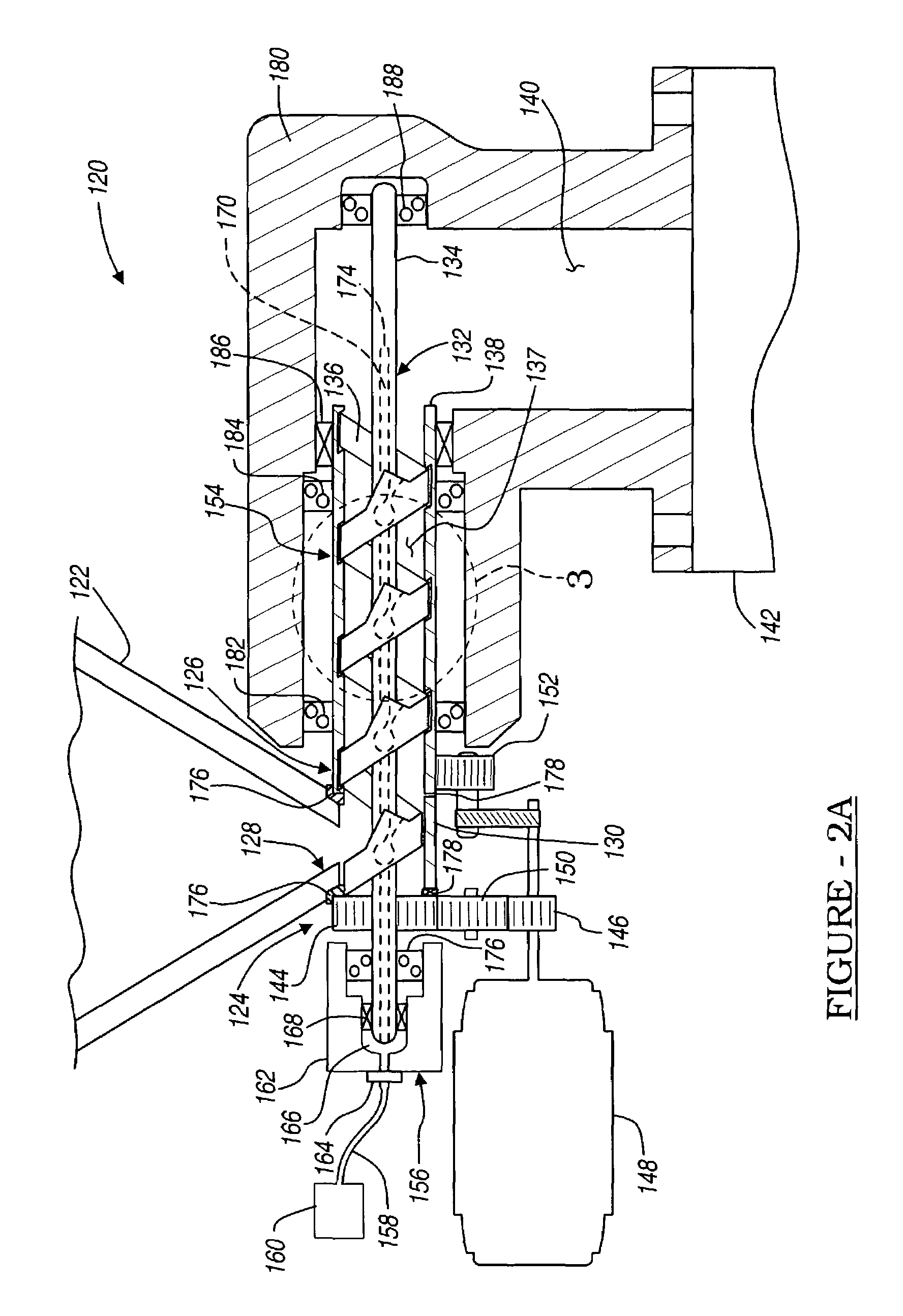
[0013]A fifth preferred embodiment of the present invention comprises a jet feeder to transport a pulverized material from a low pressure to a high pressure environment. The jet feeder has a housing to contain the material while it is within the jet feeder. The housing defines an inlet port to receive the pulverized material. An outlet port allows the material to exit the housing. A screw is disposed within the housing to advance the material from the inlet port to the outlet port. A jet port is defined on the screw. The jet port assists in moving the material to the outlet port. The pressure at the outlet port is higher than a pressure at the inlet port.
[0014]A sixth preferred embodiment of the present invention comprises a jet feeder to transport a pulverized material from a low pressure to a high pressure environment. A housing of the jet feeder contains the material while it is within the jet feeder. The housing also defines an inlet port and an outlet port. A screw is disposed within the housing to advance the material from the inlet port to the outlet port, and adapted to rotate axially in a first direction. A labyrinth seal is formed around and in communication with the screw to substantially eliminate reverse movement of the material. The pressure at the outlet port is higher than a pressure at the inlet port.

Problems solved by technology

Coal, even when highly pulverized, is substantially a solid material and difficult to pressurize to the high pressures needed for combustion.
Various systems have been developed to provide the high pressure coal required, but these systems all have numerous inefficiencies.
The carrier fluid of the slurry is also provided to the reactor as a large surplus in the slurry, thereby decreasing the efficiency of the reactor.
Nevertheless, these systems still require the unreliable cycling lock hoppers to initially increase the pressure of the slurry.
Moreover, the cycling lock hoppers generally include multiple valves and gas compressors that are inefficient and require nearly constant maintenance.
Still other systems have attempted to provide a feeder system which uses a screw feeder or pump, but has similar disadvantages.
These systems do not easily overcome the high pressure head against which the coal is pumped.

Method used


Image

  • Method and apparatus for continuously feeding and pressurizing a solid material into a high pressure system
  • Method and apparatus for continuously feeding and pressurizing a solid material into a high pressure system
  • Method and apparatus for continuously feeding and pressurizing a solid material into a high pressure system

Examples


Embodiment Construction

[0022]The following description of the preferred embodiment(s) is merely exemplary in nature and is in no way intended to limit the invention, its application, or uses.

[0023]With reference to FIG. 1, a continuous pulverized coal feed system 10 in accordance with a preferred embodiment of the present invention is illustrated. A volume of pulverized coal 11 is first held in an ambient coal silo 12. The coal silo 12 is capped with an appropriate cover 14 which includes a feed line 16. The feed line 16 may include a feed device 16a, such as a vibrator feeder, to encourage the flow of the coal into the storage silo 12. A carbon dioxide (CO2) purge line 17 provides a flow of CO2 through the coal 11 to purge atmospheric air trapped in the interstitial spaces between particles of the coal 11. The coal silo 12 includes an exit or emptying port 18. The coal 11 is coaxed or removed from the storage silo 12 through the emptying port 18 using a shaker or agitator 20. This moves the coal from ins...


PUM

PropertyMeasurementUnit
pressureaaaaaaaaaa
pressureaaaaaaaaaa
pressureaaaaaaaaaa

Abstract

A system for substantially continuously providing a solid material, for example pulverized coal, to a pressurized container. The system provides the solid material to a first container of a first pressure elevated above an initial pressure of the solid material. Generally, a screw conveyor augmented with a jet port is used to move the material where the jet port provides a gas to provide a make-up volume of the solid material. The system also provides the material to a second high pressure container after the material has been formed into a slurry. Therefore, the solid material may be substantially continuously provided in a system to a high pressure container.

Description

FIELD OF THE INVENTION[0001]The present invention relates to moving coal to a high pressure system, and more particularly to continuously feeding coal from a low pressure to a high pressure system for processing of the coal.BACKGROUND OF THE INVENTION[0002]The apparatus used in present day power generation systems typically require a high pressure coal supply system. In particular, many of these high pressure systems include high pressure reactors which combust the coal to produce heat or to further refine the carbon from the coal. The high pressure is used to nearly instantaneously combust the coal to produce the desired energy release. Coal, even when highly pulverized, is substantially a solid material and difficult to pressurize to the high pressures needed for combustion. To assist in providing the coal and achieving the high pressures required for combustion thereof, the coal is often formed into a slurry. The slurry then can be more easily pumped and pressurized to the requir...

Claims


Application Information

Patent Timeline
Patent Type & Authority Patents(United States)
IPC IPC(8): C01B3/36F23K3/00C10J3/50
CPCC10J3/50C10J2300/0969C10J2200/156
Inventor SPROUSE, KENNETH MICHAELMATTHEWS, DAVID RSTEWART, ALBERT E
Owner THE BOEING CO
Learn More