Eureka AIR delivers breakthrough ideas for toughest innovation challenges, trusted by R&D personnel around the world.

Methods and apparatus for blocking flow through blood vessels

a technology of blood vessels and blocking devices, applied in the field of medical devices, can solve problems such as unaddressed problems, inappropriate deployment of embolization coils, and deployment of typical embolization coils of the type traditionally utilized to embolise, and achieve the effect of preventing blood flow

Inactive Publication Date: 2007-12-04
CORE FITNESS SYST
View PDF73 Cites 155 Cited by
  • Summary
  • Abstract
  • Description
  • Claims
  • Application Information

AI Technical Summary

Benefits of technology

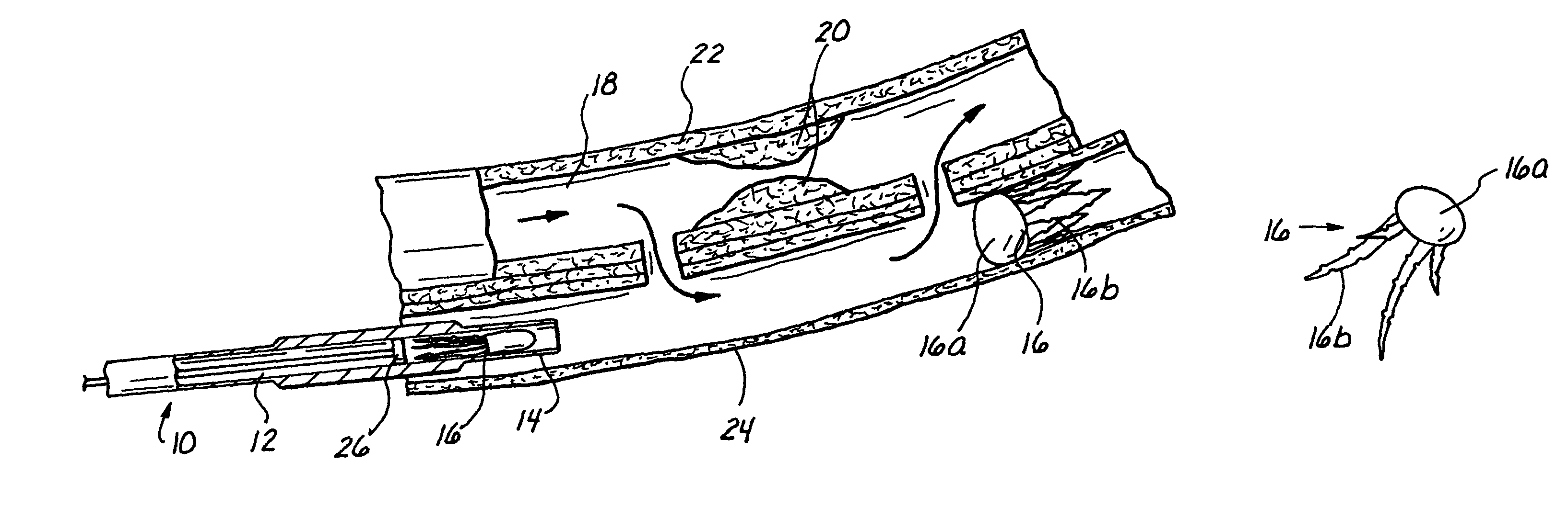
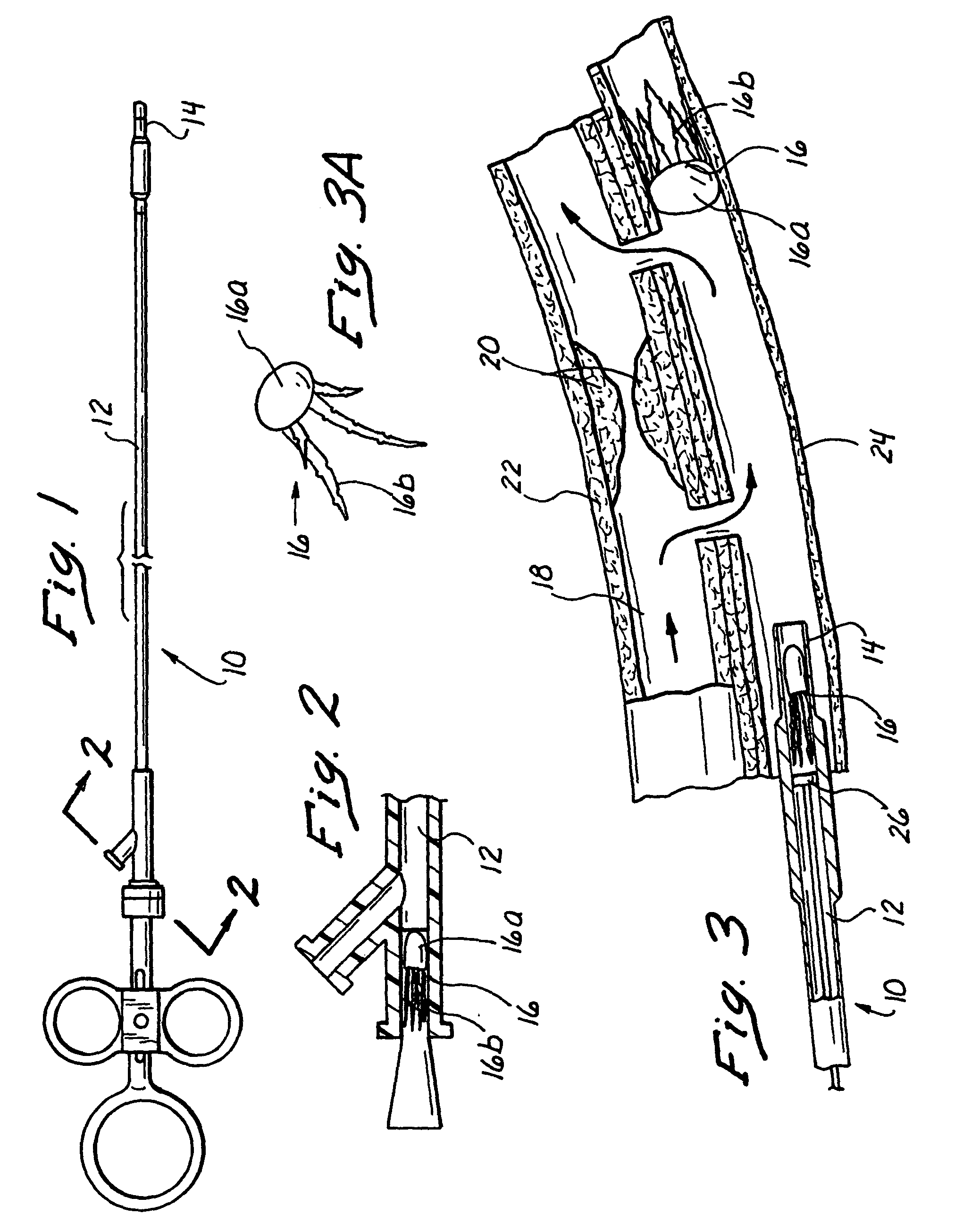
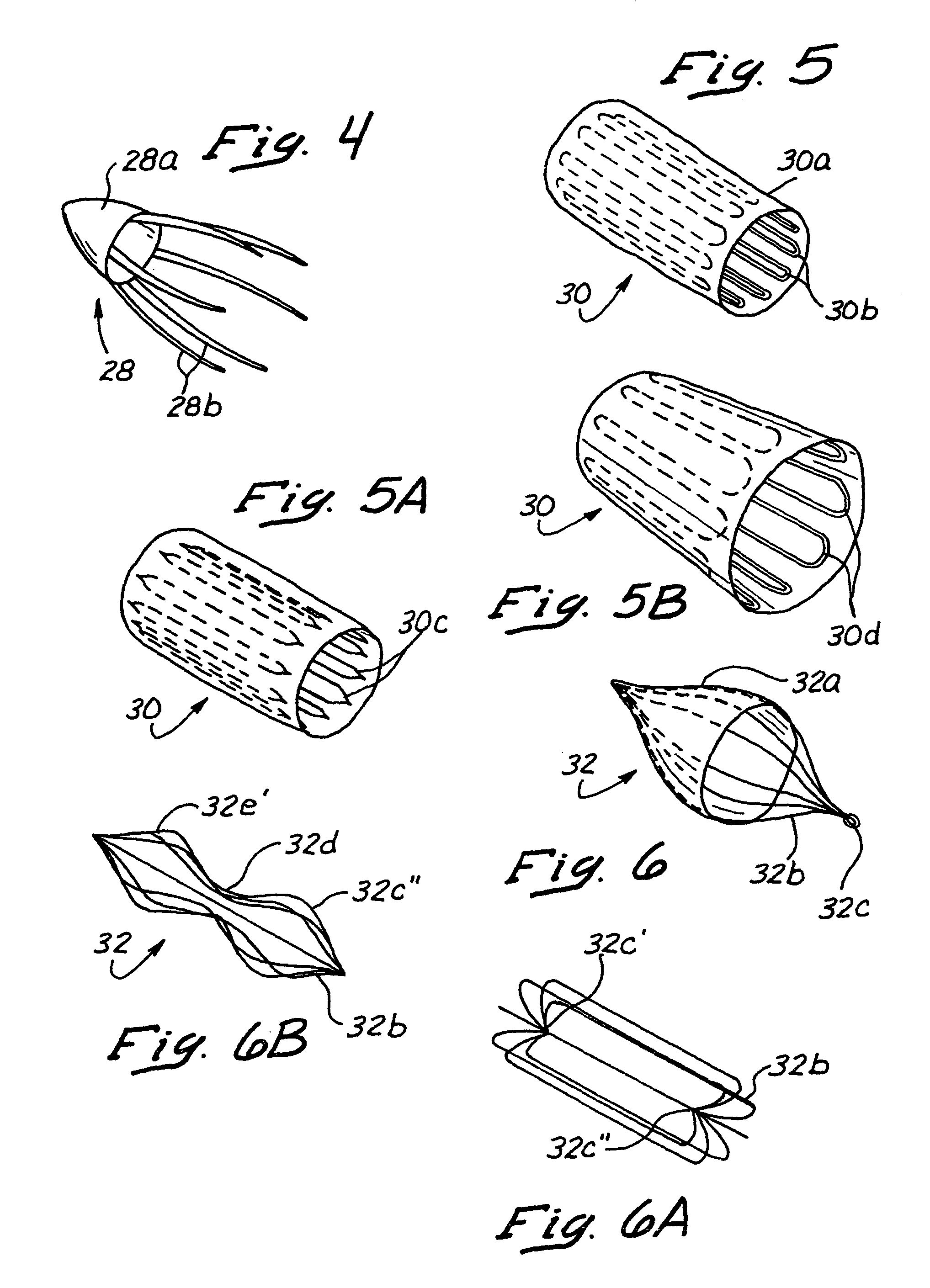
[0007]The present invention provides methods and devices for blocking or closing the lumens of blood vessels to prevent blood flow therethrough. The devices of the present invention provide certain advantages over the prior art, such as i) possible removeability following implantation and / or ii) possible puncturability or retraverseability following implantation and / or iii) the ability to provide substantially immediate and permanent blockage of flow through a tapered or widening region of a blood vessel lumen (e.g., the proximal portion of the great cardiac vein).
[0012]Still further in accordance with the invention, the vessel engaging portion of the apparatus may comprise a plurality of members which emanate outwardly from a fulcrum point such that, when pressure is applied against the fulcrum point, such pressure will cause the plurality of members to become outwardly biased and thus radially expand, enlarge or exert outward pressure against the blood vessel wall, thereby deterring the apparatus from becoming dislodged or migrating from its seated position within the blood vessel.
[0017]Still further in accordance with the invention, some embodiments of these implantable lumen-blocking apparatus may comprise a woven fabric or other tissue permeable material which will undergo cellular ingrowth or endothelialization. In these embodiments, the process of cellular ingrowth or endothelialization may be exploited to enhance the anchoring of the apparatus within the blood vessel lumen and / or to improve the long-term biocompatability of the apparatus following implantation thereof.Lumen Welding Devices
[0019]Further in accordance with this embodiment of the invention, there is provided an intraluminally insertable device which has a balloon formed thereon, a fluid delivery port, and an energy emitting region. when the balloon is inflated, the balloon will temporarily block the vessel lumen. Thereafter, a flowable conductive medium (e.g., saline solution) may be introduced through the fluid delivery port and into the vessel lumen adjacent the location of the energy emitting region. Energy is then emitted such that the energy will be transmitted through the previously introduced conductive substance, to the wall of the blood vessel, thereby resulting in shrinkage or contraction of the vessel wall so as to result in closure of the blood vessel lumen at that site.

Problems solved by technology

These transvascular, catheter-based coronary artery bypass procedures present unique and heretofore unaddressed problems relating to the type(s) of blocking apparatus which may be utilized to block the lumen of the coronary vein proximal and / or distal to the arterial-venous blood flow passageways (e.g., puncture tracts or interstitial tunnels) formed during the procedure.
This proximal segment of the Great Cardiac Vein is of tapered or angular configuration and, as a result, the deployment of typical embolization coils of the type traditionally utilized to embolize or block the lumens of blood vessels or the defined spaces of aneurysm may be inappropriate, due to the fact that such embolization coils may become dislodged or work loose due to the gradually tapered or widening anatomy of the proximal segment of the Great Cardiac Vein.

Method used


Image

  • Methods and apparatus for blocking flow through blood vessels
  • Methods and apparatus for blocking flow through blood vessels
  • Methods and apparatus for blocking flow through blood vessels

Examples


embodiment 64

[0094]Such embodiment, in addition to providing the desired vaso-occlusion, further provides the advantage of defining offshoot vessels 68 that may otherwise go undetected (i.e., difficult to visualize) due to the high blood flow rate passing through the main vessel to be occluded. As will be appreciated by those skilled in the art, such high blood flow rate has a tendency to wash out or otherwise prevent sufficient contrast media from building up to detectable concentrations in such offshoot vessels. Additionally, such embodiment 64 further advantageously allows for the infusion of embolization means while such catheter remains in place in the vessel, thus eliminating the need for additional devices and procedure in the event it is necessary to occlude such offshoot vessels.

embodiment 70

[0095]FIG. 20 depicts a three-valved stent 70 positionable within a vessel that, in addition to occluding blood flow, may be advantageously manipulated to redirect blood flow through a vessel as may be desired. In this respect, the stent 70, which may be deployed as all of the other aforementioned embodiments, namely, via expulsion through the lumen of a catheter of a desired location, is provided with three (3) valves 70a, 70b, 70c capable of occluding or facilitating blood flow. The respective valves 70a, 70b, 70c may be manipulated such that blood flow paths can be controlled at particular pressure differentials. Advantageously, such embodiment 70 may be customized to create one flow channel under one set of pressure conditions and a different flow path under different conditions.

[0096]Referring now to FIG. 21, there is shown yet a still further preferred way to achieve the desired site-specific vaso-occlusion via the deployment of a vaso-occlusive agent 72 through the distal end...

embodiment 92

[0106]Such embodiment 92 advantageously provides high biocompatability, coupled with the fact that an abundant source of such material may be readily derived from the host patient. Furthermore, the vaso-occlusion achieved by using autologous tissue has the advantage of being easily removed insofar as such tissue may be readily removed at a later time by degrading the tissue, such as by cauterizing or cutting the same, at a later date.

[0107]In an alternative embodiment, as depicted in FIG. 28, the embolic facilitator device comprises a mass of intertwined wire mesh 100, referred to herein as embolization strands, that are connected at various random points within its structure and attached to an electrode or electrodes 102 whereby such strands 100 can be sufficiently energized to cause coagulation, and hence embolization, within the lumen of the vessel. At present, it is believed that the application from 2 to 50 watts to the strands 100 is sufficient to cause the necessary coagulati...


PUM


Abstract

Methods and apparatus for occluding blood flow within a blood vessel. In a first series of embodiments, the present invention comprises a plurality of embolic devices deployable through the lumen of a conventional catheter such that when deployed, said embolic devices remain resident and occlude blood flow at a specific site within the lumen of the blood vessel. Such embolic devices comprise either mechanical embolic devices that become embedded within or compress against the lumen of the vessel or chemical vaso-occlusive agents that seal off blood flow at a given site. A second embodiment of the present invention comprises utilization of a vacuum / cauterizing device capable of sucking in the lumen of the vessel about the device to maintain the vessel in a closed condition where there is then applied a sufficient amount of energy to cause the tissue collapsed about the device to denature into a closure. In a third series of embodiments, the present invention comprises the combination of an embolization facilitator coupled with the application of an energy force to form an intraluminal closure at a specified site within a vessel.

Description

RELATED APPLICATIONS[0001]This is a continuation of application Ser. No. 09 / 117,516, filed Jan. 21, 1999 now issued as U.S. Pat. No. 6,638,293, which is based on PCT International Application PCT / US97 / 01463, which claims priority to U.S. Provisional Patent Application Ser. No. 60 / 010,614, filed on Feb. 2, 1996, which is a continuation-in part of U.S. patent applications Ser. No. 08 / 730,327, filed on Oct. 11, 1996 and now issued as U.S. Pat. No. 6,190,353; and Ser. No. 08 / 730,496, filed on Oct. 11, 1996 and now issued as U.S. Pat. No. 5,830,222.FIELD OF THE INVENTION[0002]The present invention relates generally to medical devices, and more particularly to methods and apparatus for blocking or closing the lumens of blood vessels or other anatomical conduits.BACKGROUND OF THE INVENTION[0003]In modern medical practice, it is often desirable to block or otherwise prevent flow through the lumen of a blood vessel or other anatomical conduit. Examples of medical procedures wherein it is des...

Claims


Application Information

Patent Timeline
Patent Type & Authority Patents(United States)
IPC IPC(8): A61B17/34A61B1/313A61B17/00A61B17/064A61B17/11A61B17/12A61B17/22A61B17/30A61B18/00A61B18/14A61B18/24A61B19/00A61F2/00A61F2/02A61F2/90A61M25/00
CPCA61B1/3137A61B17/11A61B17/12022A61B17/12045A61B17/12109A61B17/12131A61B17/12136A61B17/12159A61B17/12172A61B17/12186A61B17/1219A61B17/3417A61B18/1445A61F2/2493A61F2/95A61M2025/1052A61B17/00491A61B17/0643A61B17/3496A61B18/00A61B18/1477A61B18/1492A61B18/24A61B19/38A61B19/5212A61B2017/00243A61B2017/00247A61B2017/00252A61B2017/00504A61B2017/0641A61B2017/0647A61B2017/0649A61B2017/1107A61B2017/1139A61B2017/1205A61B2017/12127A61B2017/22038A61B2017/22077A61B2017/306A61B2017/347A61B2017/3488A61B2018/00392A61B2018/00404A61B2018/00869A61B2018/1425A61B2018/1475A61B2019/5276A61B2019/5425A61B2019/5429A61B2019/5458A61F2/07A61F2/90A61F2002/075A61F2002/30079A61F2002/8486A61F2210/009A61M2025/0076A61M2025/0096A61B17/00234A61B90/361A61B90/40A61B2090/378A61B2090/3925A61B2090/3929A61B2090/3958
Inventor MAKOWER, JOSHUAFLAHERTY, J. C.MACHOLD, TIMOTHY R.WHITT, JASON B.EVARD, PHILIP C.MACAULAY, PATRICK E.GARIBOTTO, JOHN T.JENSEN, MARC
Owner CORE FITNESS SYST
Why Eureka
Eureka Blog
Learn More