Image forming apparatus and transfer apparatus employing endless belt

a technology of image forming apparatus and transfer apparatus, which is applied in the direction of electrographic process apparatus, instruments, optics, etc., can solve the problem of not being able to properly read markings, and achieve the effect of preventing the occurrence of difference(s) in charging characteristics, reducing electrical resistance(s), and increasing or less equal electrical resistan

Active Publication Date: 2007-11-27
SHARP KK
View PDF8 Cites 3 Cited by
  • Summary
  • Abstract
  • Description
  • Claims
  • Application Information

AI Technical Summary

Benefits of technology

[0016]That is, embodiment(s) of the present invention are directed toward transfer apparatus(es) such as may be used for printing of monochromatic images (ordinary black-and-white printing) during which developer is transferred to paper clinging to and transported by endless belt(s). In addition, in accordance with embodiment(s) of the present invention, the ends of at least one of the roller-shaped electrically conductive component(s) may be formed from fibrous electrically conductive component(s), and the central region of at least one of the roller-shaped electrically conductive component(s) may be formed from metal roller-like structure(s) or the like possessing electrical conductivity. In other words, because the fibrous electrically conductive component(s) formed at either respective end of the metal roller-like structure(s) or the like come in contact with either respective side in the width direction of the endless belt(s) that extend past the metal roller-like structure(s) or the like in the central region, application of electric field(s) to the metal roller-like structure(s) or the like also results in application of such electric field(s) to either extreme side of the endless belt(s) that come in contact with the fibrous electrically conductive component(s), as a result of which the endless belt(s) is / are charged with prescribed electric field(s) along the full width(s) thereof. This being the case, because action of the electric field(s) reaches either extreme side of the endless belt(s) when a cleaning technique is carried out in which reverse electric field(s) is / are applied to the endless belt(s) to cause developer adhering thereto to be transferred back to the photosensitive drum(s), it will be the case that developer adhering thereto can be cleaned therefrom. This makes it possible to solve the problem in which developer adhering at either extreme side of the endless belt(s) accumulates and this acts as abrasive to abrade the surface layer(s) of the photosensitive drum(s). As a result, it is also possible to solve the conventional problem in which abrasion of surface layer(s) of the photosensitive drum(s) causes optical signal(s) to be reflected in diffuse fashion at surface layer portion(s) of the photosensitive drum(s), making it impossible to properly read markings.
[0028]In accordance with embodiment(s) of the present invention as described above, arrangement of fibrous electrically conductive component(s) at end(s) of roller-shaped electrically conductive component(s) applying electric field(s) to endless belt(s) makes it possible to apply electric field(s) along the full width(s) of endless belt(s), permitting improvement in ability to clean developer remaining on endless belt(s), permitting elimination of variation in load in width direction(s) of rotating endless belt(s), and permitting elimination of endless belt meander as well as cracking. That is, because the fibrous electrically conductive component(s) formed at either respective end of the metal roller-like structure(s) or the like come in contact with either respective side of the endless belt(s) that extend past the metal roller-like structure(s) or the like in the central region, application of electric field(s) to the metal roller-like structure(s) or the like also results in application of such electric field(s) to either extreme side of the endless belt(s) that come in contact with the fibrous electrically conductive component(s), as a result of which the endless belt(s) is / are charged with prescribed electric field(s) along the full width(s) thereof. This being the case, because action of the electric field(s) reaches either extreme side of the endless belt(s) when a cleaning technique is carried out in which reverse electric field(s) is / are applied to the endless belt(s) to cause developer adhering thereto to be transferred back to the photosensitive drum(s), it will be the case that developer adhering thereto can be cleaned therefrom. This makes it possible to solve the problem in which developer adhering at either extreme side of the endless belt(s) accumulates and this acts as abrasive to abrade the surface layer(s) of the photosensitive drum(s). Furthermore, in accordance with embodiment(s) of the present invention, contact of either extreme side of endless belt(s) by fibrous electrically conductive component(s) makes it possible to definitively prevent meander in width direction(s) of endless belt(s).

Problems solved by technology

As a result, it is also possible to solve the conventional problem in which abrasion of surface layer(s) of the photosensitive drum(s) causes optical signal(s) to be reflected in diffuse fashion at surface layer portion(s) of the photosensitive drum(s), making it impossible to properly read markings.

Method used


Image

  • Image forming apparatus and transfer apparatus employing endless belt
  • Image forming apparatus and transfer apparatus employing endless belt
  • Image forming apparatus and transfer apparatus employing endless belt

Examples


embodiment 1

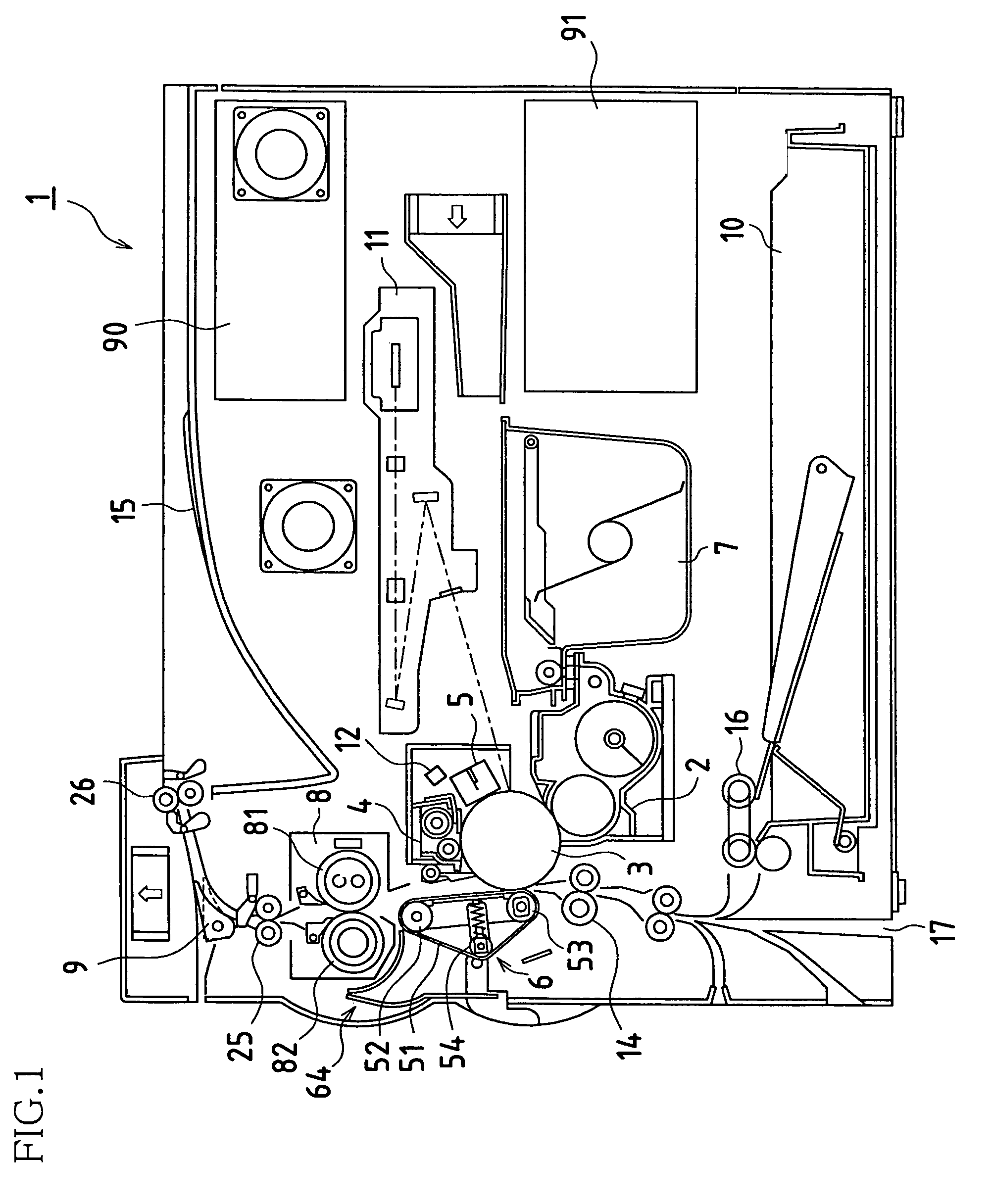
[0036]FIG. 1 is an explanatory diagram showing constitution of an image forming apparatus associated with the present first embodiment.

[0037]That is, this image forming apparatus 1 records and outputs in image form images read by image capturing apparatus(es) (read unit(s), not shown) and / or data received from equipment (e.g., personal computer(s) or other such image processing apparatus(es)) externally connected to image forming apparatus 1, and is equipped with transfer apparatus(es) such as may be used for printing of monochromatic images (ordinary black-and-white printing) during which developer (toner) is transferred to paper clinging to and transported by endless belt(s).

[0038]At this image forming apparatus 1, respective processing units carrying out various functions for image formation are arranged about photosensitive drum(s) 3, these processing units constituting image forming unit(s). That is, this image forming apparatus 1 is provided with image forming unit(s) in which...

embodiment 2

[0057]FIG. 3 is an explanatory diagram showing constitution of an image forming apparatus associated with the present second embodiment.

[0058]The present image forming apparatus 100, which forms polychromatic and / or monochromatic images on prescribed paper (recording paper) in correspondence to image data transmitted thereto from the exterior, comprises, as shown in the drawing, exposing unit(s) 101; development unit(s) 102; photosensitive drum(s) 103; cleaning unit(s) 104; charging unit(s) 105; intermediate transfer belt unit(s) (what is referred to in the context of the present invention as transfer apparatus(es)) 108, being endless belt(s); fuser unit(s) 112; paper transport path(s) S; media supply tray(s) 110; discharge tray(s) 115; and so forth.

[0059]Moreover, image data handled by the present image forming apparatus 100 corresponds to color images utilizing the respective colors black (K), cyan (C), magenta (M), and yellow (Y). Accordingly, there are four each of development u...


PUM


Abstract

Transfer roller(s) is / are such that either end thereof is formed from fibrous electrically conductive component(s) and such that cylindrical portion(s) in central region(s) is / are, for example, formed from metal roller-like structure(s), either fibrous electrically conductive component outer end being arranged so as to extend somewhat beyond either transfer / transport belt side. Furthermore, outside diameter(s) approximated by tips of respective individual fiber(s) of fibrous electrically conductive component(s) is / are somewhat larger than diameter(s) of metal roller-like structure(s). This makes it possible for electric field(s) to be applied, and for charging to occur, along the full width(s) of transfer / transport belt(s).

Description

BACKGROUND OF INVENTION[0001]This application claims priority under 35 USC 119(a) to Patent Application No. 2004-267268 filed in Japan on 14 Sep. 2004, the content of which is hereby incorporated herein by reference in its entirety.[0002]The present invention relates to copiers, facsimile machines, printers, and other electrophotographic image forming apparatuses; more particularly, the present invention pertains to a transfer apparatus employing endless belt(s) with which image forming apparatus(es) may be equipped.[0003]Image forming apparatuses making use of endless belts have become widespread in recent years. Furthermore, endless belts are frequently utilized within image forming apparatuses at fuser apparatuses, transfer apparatuses, processing units, and the like.[0004]For example, along with the increased speeds of color image forming apparatuses that have undergone rapid development in recent years, endless belts have been used as intermediate transfer bodies in the context...

Claims


Application Information

Patent Timeline
Patent Type & Authority Patents(United States)
IPC IPC(8): G03G15/20
CPCG03G15/1685
Inventor TAKIGUCHI, TOSHIKIMASUDA, YOSHIAKISHIMAZU, FUMIOMURAI, HIROYUKIYAMAUCHI, HIROKAZU
Owner SHARP KK
Why Eureka
Try Eureka