
Lens barrel for camera

a technology for lens barrels and cameras, applied in the field of lens barrels for cameras, can solve the problems of a lens barrel component not being able to ensure a sufficient level of the wide width of the flexible board, so as to achieve the effect of sufficient strength of the rotating barrel

Active Publication Date: 2007-11-27
CANON KK
View PDF5 Cites 10 Cited by
  • Summary
  • Abstract
  • Description
  • Claims
  • Application Information

AI Technical Summary

Benefits of technology

This design ensures the strength of the rotating barrel is maintained while allowing for the integration of additional electrical connections, reducing the barrel's outer dimensions and enhancing its structural integrity, thus addressing the issue of enlarged dimensions and strength deficiencies in existing systems.

Problems solved by technology

However, in a lens barrel of the type wherein other units requiring electrical connection to the camera body, such as a focusing unit and an anti-shaking unit, are also attached to the second group unit 102 within the lens barrel in addition to the shutter and diaphragm unit 103, the above-described known structure has disadvantages in that the width (indicated by a in FIG. 17) of the flexible board is increased and the outer dimension of the lens barrel is enlarged.
Therefore, the strength of the rotating barrel 107 as one of the lens barrel components cannot be ensured at a sufficient level.

Method used


Image

  • Lens barrel for camera
  • Lens barrel for camera
  • Lens barrel for camera

Examples


Embodiment Construction

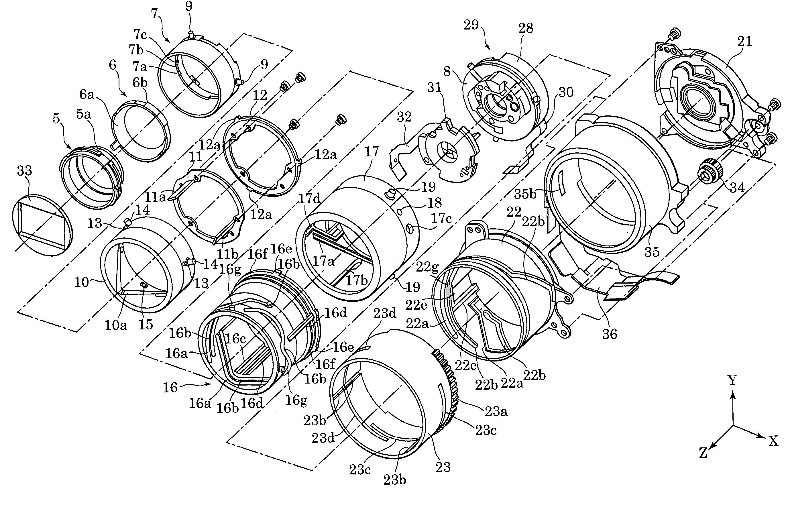
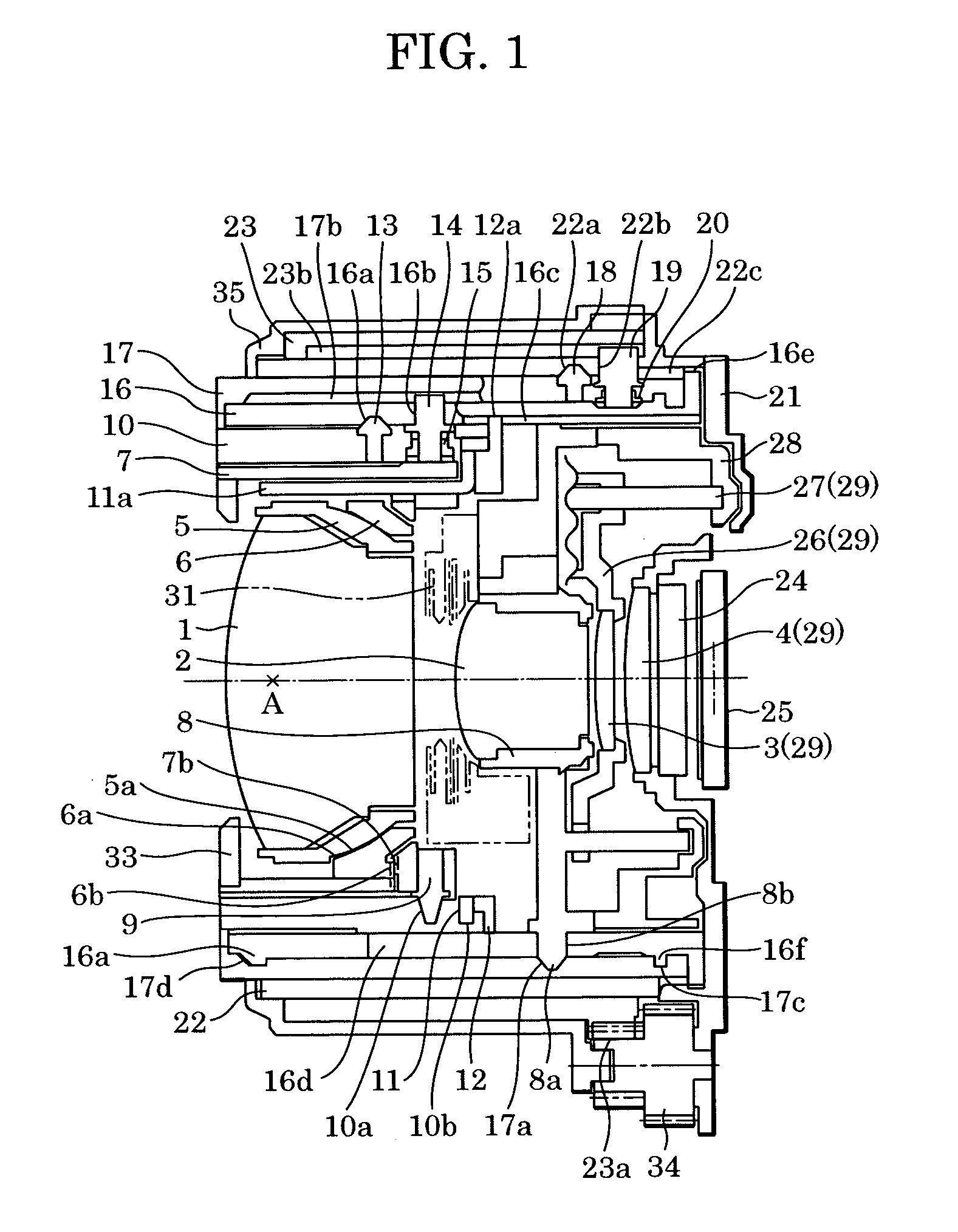
[0030]FIG. 1 is a sectional view of a zoom lens barrel in a storage position according to one embodiment of the present invention, and FIG. 9 is an exploded perspective view of the overall lens barrel. A zoom lens includes a first lens group 1, a second lens group 2, a third lens group 3, and a fourth lens group 4. The first lens group 1 is held by a first lens group holder 5 having a spherical surface 5a about a rear principal point A of the first lens group 1. A first group moving member 6 is movable in the direction of an optical axis and holds the first lens group holder 5. The outer diameter of the first group moving member 6 and the inner diameter of a first group holding member 7 are selected such that the outer periphery of the former and the inner periphery of the latter are engaged with each other. The first group moving member 6 has a conical surface 6a in contact with the spherical surface 5a. The first group holding member 7 holds the first group moving member 6 and has...


PUM


Abstract

Flexible printed boards are introduced to a camera body respectively through a plurality of slit holes formed in a rotating barrel at different positions in the direction of an optical axis. The outer dimension of the lens barrel is kept from increasing.

Description

BACKGROUND OF THE INVENTION[0001]1. Field of the Invention[0002]The present invention relates to a lens barrel for a camera, and more particularly to a mounting structure of a flexible printed board which is mounted in a lens barrel for a camera.[0003]2. Description of the Related Art[0004]FIG. 16 is a schematic sectional view showing a mounting structure of a flexible printed board (also referred to as a “flexible board”) for electrically connecting, to a camera body, a shutter, a diaphragm, a focusing mechanism, etc., which are disposed within a known retracting zoom lens barrel, and FIG. 17 is a schematic view of the zoom lens barrel from the front side.[0005]Referring to FIG. 16, the zoom lens barrel comprises a first group unit 101 and a second group unit 102. A shutter and diaphragm unit 103 is attached to the second group unit 102. A rectilinearly moving barrel 104 guides the first group unit 101 and the second group unit 102 in the direction of an optical axis. A cam barrel ...

Claims


Application Information

Patent Timeline
Patent Type & Authority Patents(United States)
IPC IPC(8): G03B7/26G02B7/10G02B7/02G03B5/00G03B9/02G03B9/08G03B17/00G03B17/02G03B17/04H04N5/225H05K1/00
CPCG02B7/102G03B9/02G03B17/04H04N5/2254G03B9/08H05K1/0393H04N23/55
Inventor TSUJI, KANJI
Owner CANON KK
Learn More