
Protective case for information storage disc

a protective case and information storage technology, applied in the field of protective cases, to achieve the effect of increasing structural strength, facilitating opening the case, and reducing mechanical damag

Inactive Publication Date: 2007-11-27
OSBORN WARREN R +1
View PDF10 Cites 5 Cited by
  • Summary
  • Abstract
  • Description
  • Claims
  • Application Information

AI Technical Summary

Benefits of technology

The solution significantly increases the case's resistance to mechanical damage, supports the lid under crushing loads, and allows for clear graphic displays while maintaining a low manufacturing cost, ensuring the case remains functional and aesthetically appealing during handling and shipping.

Problems solved by technology

Although it is assumed that a small percentage of the cases will be damaged in the mailing process, it is believed that an overwhelming great majority will arrive at their destination without damage.

Method used


Image

  • Protective case for information storage disc
  • Protective case for information storage disc
  • Protective case for information storage disc

Examples


first embodiment

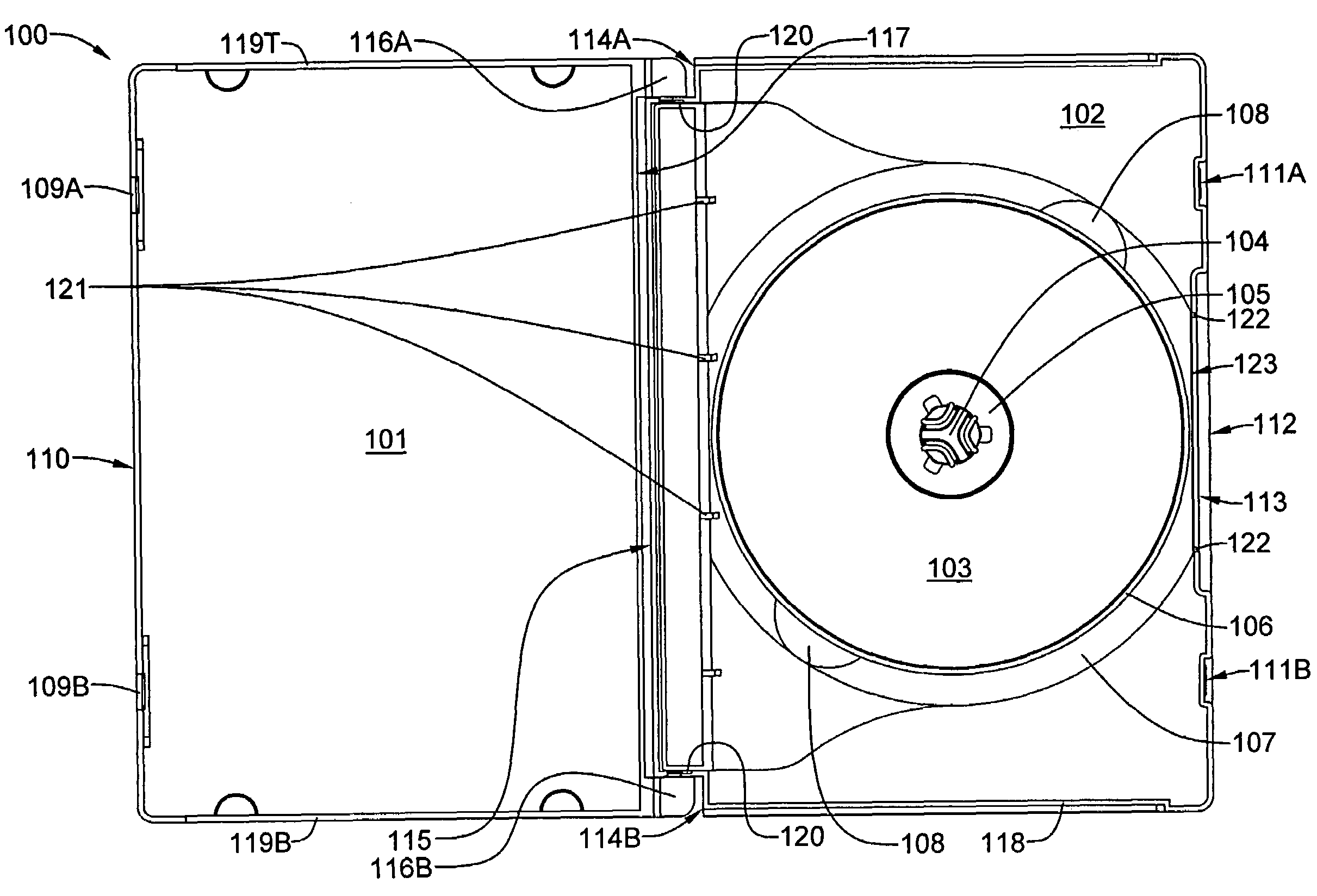
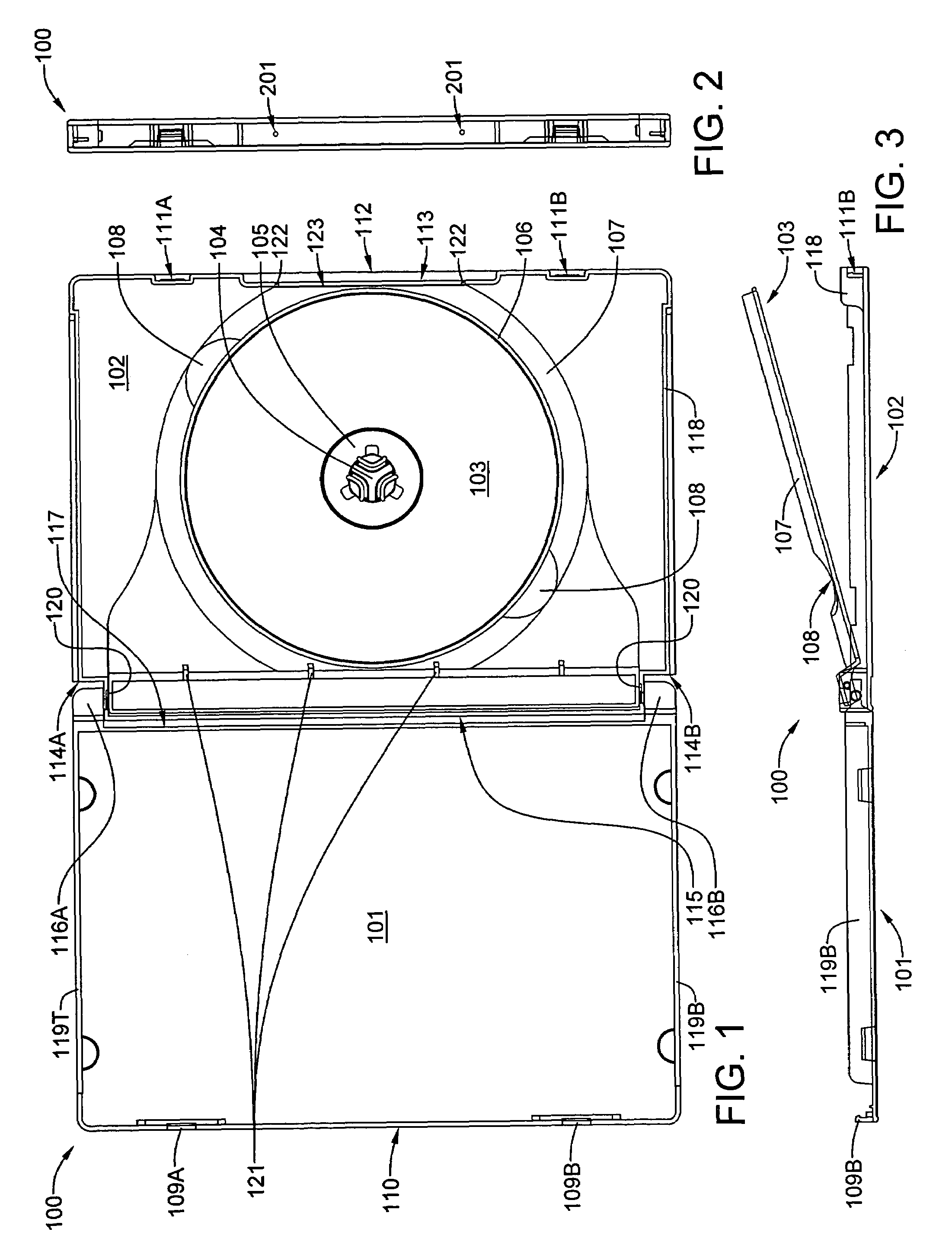
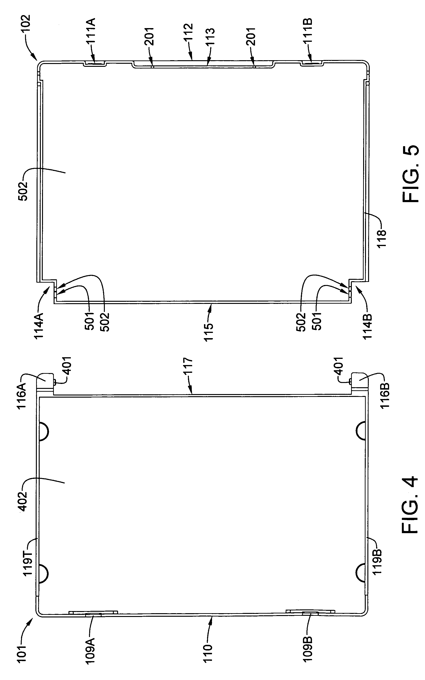
[0041]Still referring to FIG. 1, it will be noted that the base member 101 incorporates a pair of hinge alcoves 114A and 114B, which are located at opposite ends of the rear edge 115 of the base member 102. It will also be noted that the lid member 101 incorporates a pair of hinge arms 116A and 116B located at opposite, adjacent corners on the rear edge 117 of the lid member 101. The lid member 101 and the base member 102 are hingeably coupled via a system of axially-aligned studs and apertures. For the preferred embodiment, each of the hinge alcoves 114A and 114B incorporates a cylindrical aperture that is axially aligned with the cylindrical aperture of the other hinge alcove. Each of the hinge arms 116A and 116B incorporates a pivot stud that is axially aligned with the pivot stud of the other hinge arm. By slightly distorting the lid member 101, the base member 102, or both, the lid member 101 can be pivotally attached to the base member 102. It will be further noted that the ba...

second embodiment

[0050]Referring now to FIGS. 11 and 12, the hinge arm 116A of FIGS. 9 and 10 has been modified to remove additional polymeric plastic material by forming dimples in the upper and lower surfaces thereof. The modified second embodiment hinge arm 1101A is still solid from side to side through the pivot axis 1103.

[0051]Referring now to FIGS. 13 and 14, a third embodiment hinge arm 1301A retains the full height H2 of the jewel case. However, polymeric plastic material has been removed in the well 1302 shown in FIG. 13 and in the valley 1401 shown in FIG. 14. Nevertheless, the third embodiment hinge arm 1301A is still solid from side to side through the pivot axis 1103.

[0052]Referring now to FIGS. 15 and 16, a second embodiment media tray 1501 completely covers the inner surface of base member 102. This may be an advantageous feature when a paper base member insert or label is used, as media tray 1501 will completely cover a full-size insert. Other than size, the primary difference betwee...


PUM


Abstract

A three-piece jewel case for information storage discs, such as CDs and DVDs, is of the clam-shell type, and includes a base portion having a pair of generally rectangular hinge recesses positioned at adjacent corners along a rear side edge thereof, a lid portion having a pair of generally rectangular hinge arms positioned at adjacent corners along a rear side edge thereof, and a media tray having a lid portion supporting hub, which snaps into the base portion. For a preferred embodiment of the case, the media tray is hingeably connected to the base portion along the rear side edge. Each hinge arm has a rectangular solid component that extends from the outer edge to the inner edge and from the front edge to the back edge thereof. This feature rigidifies the rectangular hinge so that it is much more resistant to mechanical damage from crushing or dropping loads.

Description

BACKGROUND OF THE INVENTION[0001]1. Field of the Invention[0002]The invention relates generally to protective cases for storing and shipping disc-shaped information storage media such as compact discs and digital video disks and, more particularly to protective jewel cases of a clam-shell design comprising an assembly of three pieces: a bottom cover piece, a top cover piece hingeably connected to the bottom cover piece, and an internal swing-out piece hingeably connected to the bottom cover piece.[0003]2. History of the Prior Art[0004]The use of optically-scannable discs for high-density storage of digital data has exploded since the advent of the compact disc (CD) in 1983. Capable of storing 650 to 700 megabytes of digital data, a single CD could hold 74 to 80 minutes of high-quality music. Fourteen years later, the digital video disc (DVD) was introduced. Although a DVD is identical in thickness (1.2 millimeters) and diameter (120 millimeters or 4.7 inches) to a standard CD, the D...

Claims


Application Information

Patent Timeline
Patent Type & Authority Patents(United States)
IPC IPC(8): B65D85/57
CPCG11B33/0427
Inventor OSBORN, WARREN R.DUNFORD, BRYAN P.
Owner OSBORN WARREN R
Learn More