
Safety cap

a safety cap and cap body technology, applied in the field of safety caps, can solve the problems of increasing the child-resistantness of the cap, deteriorating the appearance of the cap, and up user's feelings of trouble, so as to improve the child-resistant effect and facilitate the streamlined appearance of the safety cap

Inactive Publication Date: 2007-11-20
YOSHINO KOGYOSHO CO LTD
View PDF16 Cites 20 Cited by
  • Summary
  • Abstract
  • Description
  • Claims
  • Application Information

AI Technical Summary

Benefits of technology

The present invention provides a safety cap for containers that can be opened and closed repeatedly. The cap has a stopping piece that can be pushed inwardly to open the container, and a cover that can be opened and closed repeatedly. The cap can also have a hinge and a stopping piece that can be swung outwardly to open the container. The cap can be designed to resist unauthorized opening by children, and it can be opened without pressing the stopping piece inwardly. The cap can also have a sliding member that can move up and down to open and close the container. The invention also provides a safety cap that cannot recover to its initial state after opening, showing an obvious sign of unauthorized opening.

Problems solved by technology

However, since the lower plate portion of operation plate is exposed to the outside as a push button, the appearance of the cap is deteriorated and the dust is apt to be attached to the lower plate portion of the operation plate, which may be disadvantage in accordance with the usage of the cap.
Although the complexity in its operation contributes to prevent unintentional opening of the cap by the small children (including infants) for example, thereby increasing the cap' childproofness, it is natural that the grown-up user feels it troublesome especially when he or she has to repeat the opening operation for the repeated use of the container under the circumstances there is no chance of unintentional use of the children.

Method used


Image

  • Safety cap
  • Safety cap
  • Safety cap

Examples


Embodiment Construction

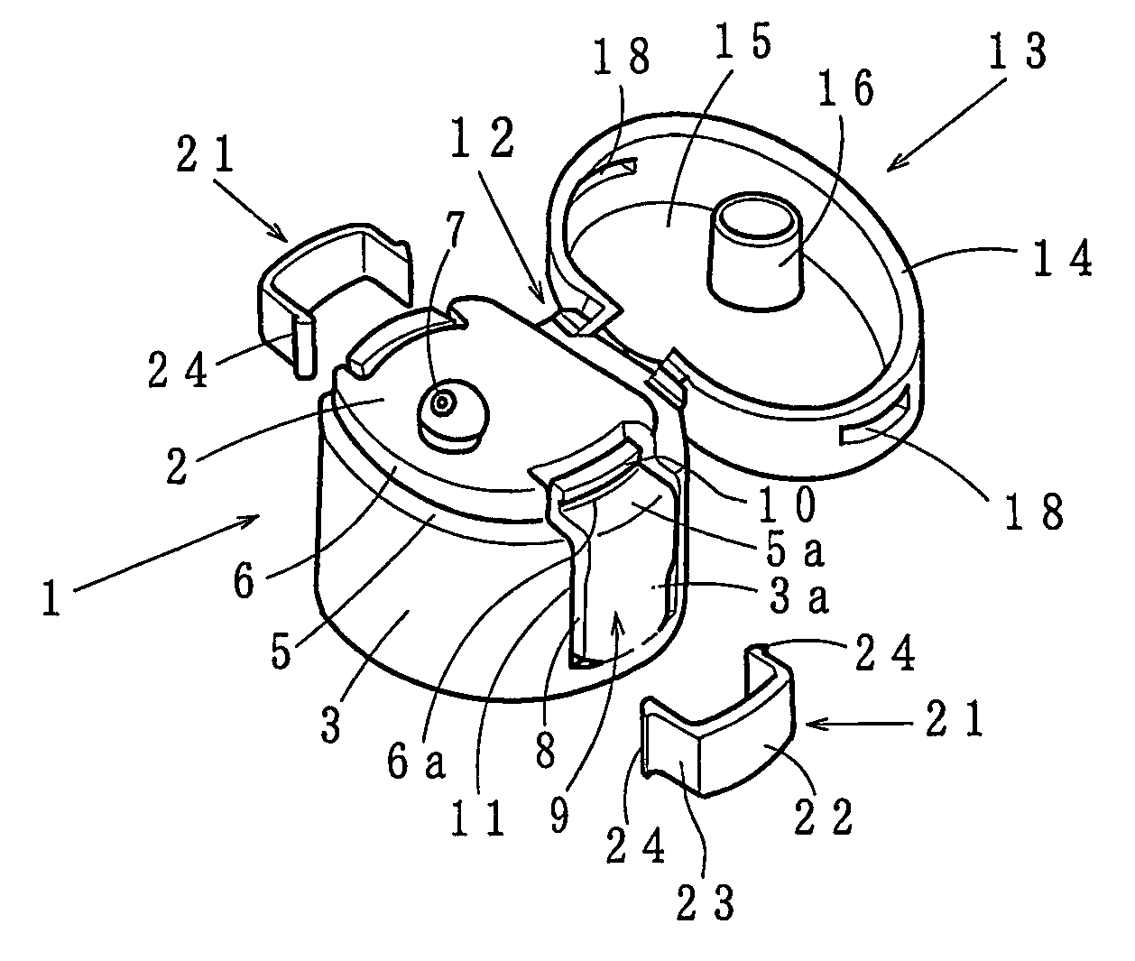
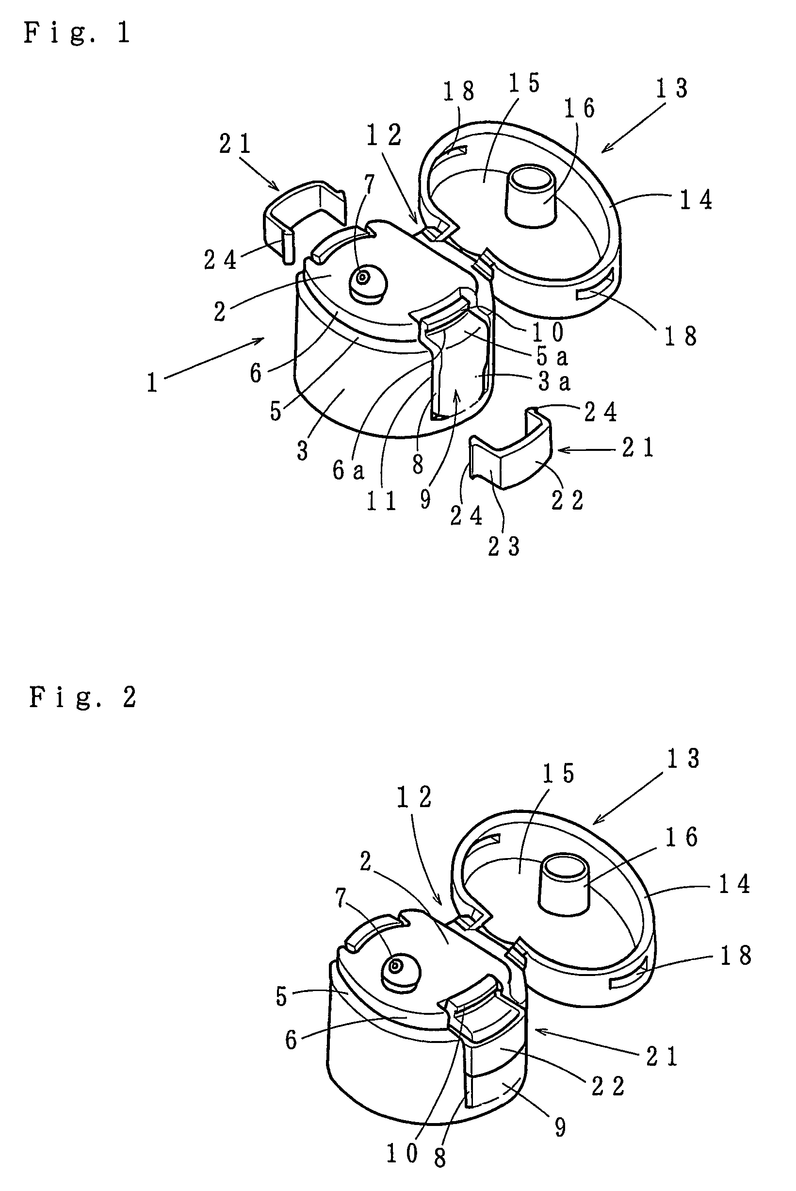
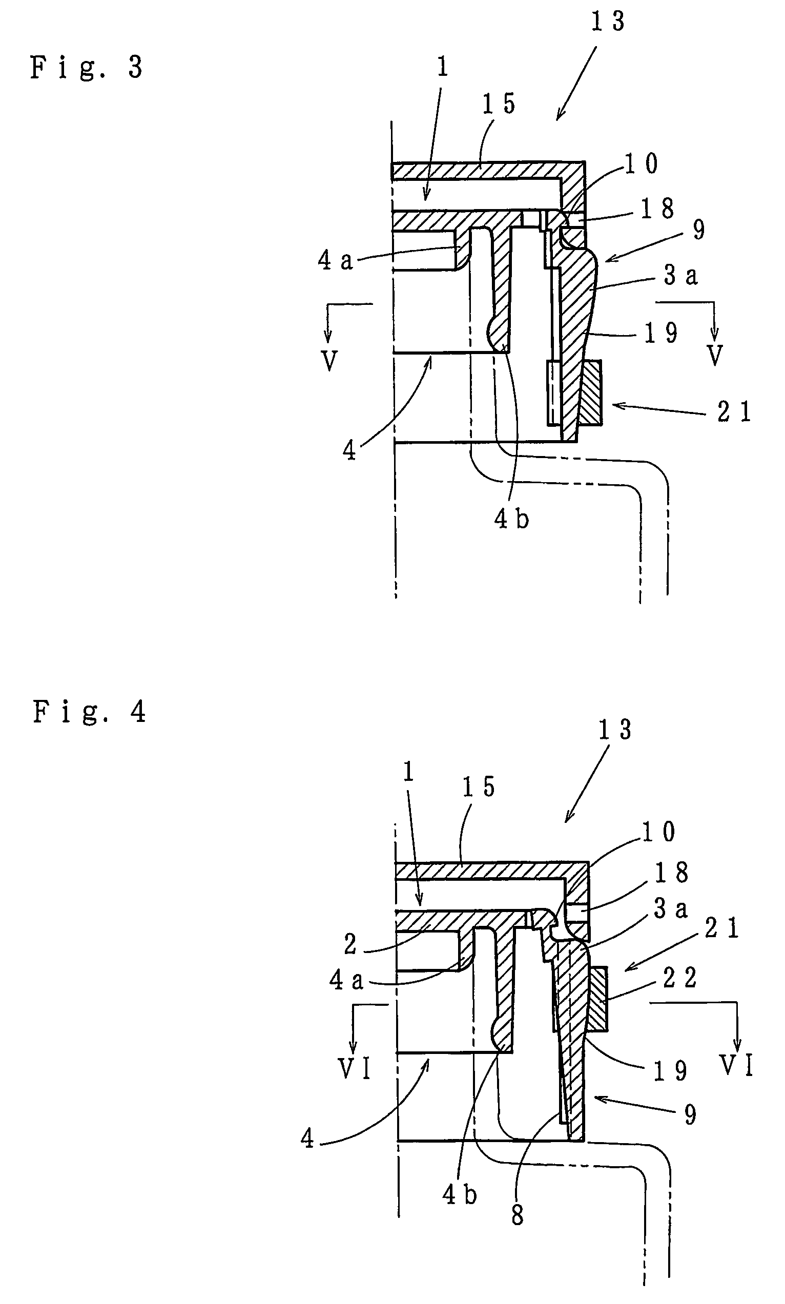
[0044]FIGS. 1 to 6 show a first embodiment of the safety cap according to the present invention.

[0045]Referring briefly on the elements of the safety cap which are common with the prior art. Numeral 1 designates a cap body having a top wall 2 and a skirt (or an outer circumferential wall) 3 depending from the perimeter of the top wall. The top wall 2 is provided at its under side with inner circumferential wall(s) 4 depending therefrom for fitting to an opened neck portion of a container as shown in FIGS. 3 and 4. The inner circumferential walls may be a sealing cylinder 4a for fitting within the opened neck portion, and a holding cylinder 4b for fitting on the opened neck portion. The upper end portion of the cap body 1 is preferably formed into a small diameter portion 6 with a step portion 5 with its surface directed upwardly being intermediate the upper end portion and the remainder of the cap body 1. The top wall 2 is provided at its front portion with a discharge spout 7 from ...


PUM


Abstract

A child resistant safety cap having a cover and a safety mechanism by which finger dexterity is required to open the cap, while the safety mechanism capable of being released if it is unnecessary. The cap comprises a cap body 1 having a skirt 3 with at least one stopping piece 9 at one side thereof. The stopping piece 9 has a base end fixed to a lower portion of the skirt 3 such that the stopping piece is pushable inwardly and swayable about the base end. The leading end portion of the stopping piece 9 is confronting at its outside with the insides of an outer tube 14 of the cover, and first and second engagement means 10, 18 are provided at confronting sides of the stopping piece 9 and the outer tube 14 for providing mutual engagement, such that when the stopping piece 9 is in an initial position, the first and second engagement means 10, 18 are engaged unless the stopping piece 9 is pushed inwardly against its elasticity. The stopping piece is adapted to move to a second position where the first and second engagement means are separated without pushing the stopping piece.

Description

TECHNICAL FIELDS[0001]The present invention relates to a safety cap, in particular, a safety cap with a cover unopenable unless a specific opening operation is taken place.PRIOR ART[0002]Conventionally, as a cap for a container for a drink or other contents, there is proposed a cap having a cylindrical body for fitting on an opened neck portion of the container, and a cover for closing the top end surface of the cylindrical body. Although such a cap is easy to open for everybody, but it may be opened by a mischief small child such that the contents of the container may be scattered therearound. Moreover, the cap is susceptible to an unauthorized opening which may result in pilfering of the contents by unauthorized persons.[0003]For preventing these disadvantages, there are following proposals on safety caps which are not able to open without taking a specific open operation that requires the finger dexterity of the grownups.[0004]For example, Japanese Utility Model Publication No. 5...

Claims


Application Information

Patent Timeline
Patent Type & Authority Patents(United States)
IPC IPC(8): B67B5/00B65D41/16B65D50/08B65D47/08B65D50/04B65D50/06
CPCB65D47/0814B65D50/067B65D50/046B65D50/045
Inventor HAYAKAWA, SHIGERUGOTO, TAKAYUKI
Owner YOSHINO KOGYOSHO CO LTD
Learn More