Display apparatus and display method

Inactive Publication Date: 2007-11-13
SHARP KK
View PDF14 Cites 15 Cited by
  • Summary
  • Abstract
  • Description
  • Claims
  • Application Information

AI Technical Summary

Benefits of technology

[0011]The present invention is made in view of the forgoing problems, and has an object of providing a display apparatus and display method whose display quality is improved by moving a partial display area without affecting an image displayed in an area other than the partial display area.
[0014]According to the above arrangement and the above method, by moving the partial display area to the predetermined position within the display screen of the image display section when the predetermined time lapses, it is possible to prevent sticking of the image on the image display section. Hereby, it is possible to prevent deterioration of display quality due to the sticking of the image on the image display section.
[0016]Further, in the case where the partial display area is moved for preventing the sticking of the image, in an area to which the partial display area is moved, data stored in a partial screen memory is read out and the data that has been written in the area is overwritten with the data thus read out. In an area from which the partial display area has moved out, data stored in a whole screen memory is read out, and the data that has been written in the area is overwritten with the data thus read out. Therefore, the movement of the partial display area within the display screen of the image display section does not affect the image displayed on the area other than the partial display area.
[0017]Therefore, according to the above arrangement and the method, because the movement of the partial display area does not affect the image that is desired by the user and is displayed on the area other than the partial display area, the display quality for the case where the image display is performed on both the partial display area and the other display area, that is, the display quality of the image display section can be improved.
[0019]In this case, power consumption is higher in the partial display area than in the area other than the partial display area, because it is necessary that the data be updated sequentially in the partial display area. However, in the area other than the partial display area, after the writing of the data, the data is held for a predetermined (holding) period longer than data update interval (that is, a refresh interval) of the partial display area, and then refreshed. Therefore, it is possible to reduce overall power consumption.
[0020]Therefore, according to the above arrangement and method, the power consumption is lowered compared with a case where the whole image display section is the partial display area, and as a result, the overall power consumption of the display apparatus and the display method are lowered.

Problems solved by technology

Such high definition and full color display gives the liquid crystal display apparatuses a higher power consumption.
That is, the portable telephone using a conventional partial driving method is poor in versatility and attractiveness, because content to be displayed on the display screen of the liquid crystal display apparatus during a waiting period is fixed.
However, the art disclosed in the publication has the following problems.
Because of this, it is impossible to display on the inactive area an image that a user desires.
This deteriorates display quality of the display screen.

Method used


Image

  • Display apparatus and display method
  • Display apparatus and display method
  • Display apparatus and display method

Examples


first embodiment

[0035]One embodiment of the present invention will be described below. Note that the present embodiment explains a case where the present invention is adopted in a liquid crystal display apparatus that is a hold-type display apparatus for performing image display, in which data is held on a display section for a predetermined period.

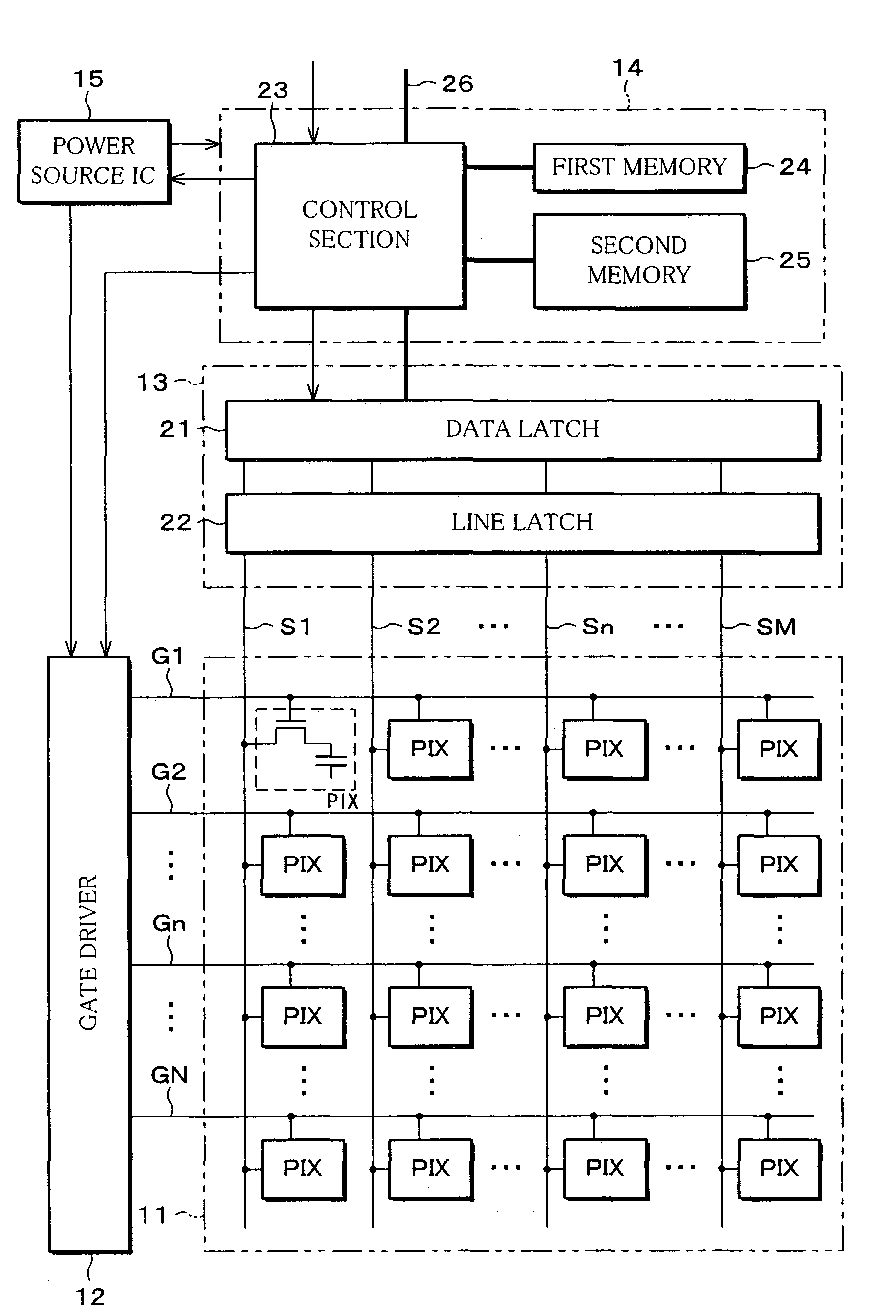
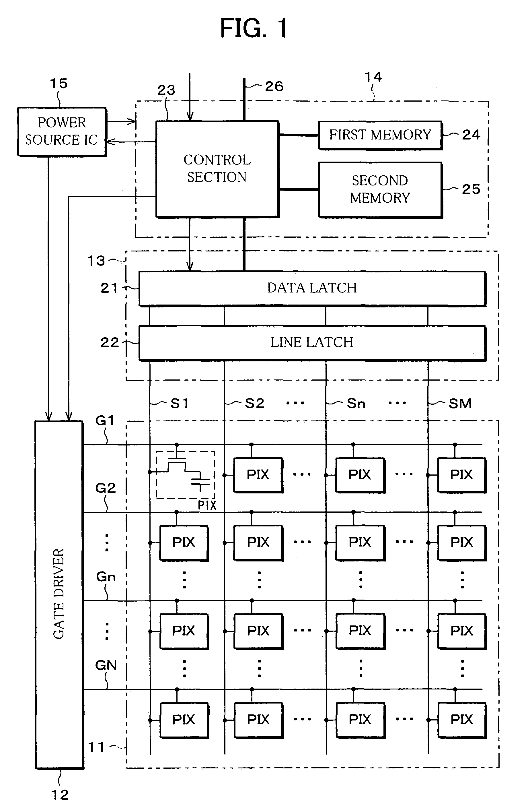
[0036]The liquid crystal display apparatus of the present embodiment is, as shown in FIG. 1, provided with (i) a display section 11 including a liquid crystal panel, (ii) a gate driver 12 and a source driver 13 as driving circuits for driving the display section 11, (iii) a control IC (Integrated Circuit) 14 for sending (transmitting) an image signal and a control signal to the source driver 13, and (iv) a power source IC (Integrated Circuit) 15 for sending, to the gate driver 12 and the control IC 14, a control signal for driving.

[0037]In the display section 11, an N number of gate lines G1, G2, . . . , Gn, . . . , GN (hereinafter, the gate lines are re...

second embodiment

[0100]Another embodiment of the present invention is described below. Note that the present embodiment describes a case where the present invention is adopted in a liquid crystal display apparatus which is a hold-type display apparatus, as the first embodiment. Moreover, sections having the same functions as in the first embodiment are labeled in the same fashion, and their explanation is omitted here.

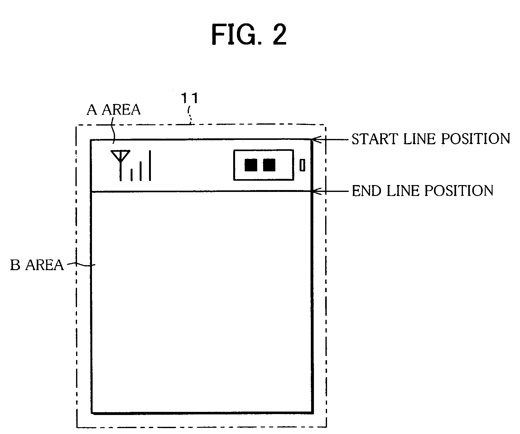
[0101]The liquid crystal display apparatus of the present embodiment is provided with a display section 11 shown in FIG. 11.

[0102]In the display section 11, an A area that is a partial display section is positioned substantially at a middle of the display screen, and border lines 31 and 32 are border lines between the A area and a B area that is a still image display section. The border line 31 indicates a start line position, whereas the border line 32 indicates an end line position. The border lines 31 and 32 are displayed as white lines or black lines.

[0103]For example, where the st...


PUM


Abstract

A display apparatus of the present invention is provided with (i) a second memory for storing therein data of one frame for a whole display area of a display section, (ii) a first memory, provided in addition of the second memory, for storing therein data of one frame for a partial display area, (iii) a control section for causing the data respectively read out from the memories, to be respectively written in the display areas to which the data correspond to, and casing the partial display area to move to an predetermined position within a display screen of the display section, when a predetermined time lapses. The display apparatus has an improved display quality by moving the partial display area without affecting an image displayed in an area other than the partial display area.

Description

FIELD OF THE INVENTION[0001]The present invention relates to a display apparatus and a display method using a partial driving method in which part of a display screen is activate and the other part is inactivate, relating to a hold-type display apparatus such as a liquid crystal display apparatus.BACKGROUND OF THE INVENTION[0002]Liquid crystal display apparatuses, which have been improved to have high definition and full color display, are mainly used as display apparatuses for use in portable telephones as portable terminal apparatuses. Such high definition and full color display gives the liquid crystal display apparatuses a higher power consumption.[0003]Further, in such portable telephones, reduction in power consumption of the liquid crystal display apparatuses lowers overall power consumption of the portable telephones.[0004]For those reasons, a partial driving method has been suggested. The partial driving method is a driving method in which part of a screen of a liquid cryst...

Claims


Application Information

Patent Timeline
IPC IPC(8): G09G3/36G02F1/133G09G3/20G09G5/00H04M1/00H04M1/02
CPCG09G3/3666G09G3/367G09G2330/021G09G2320/043G09G2310/04G02F1/133
Inventor NAKANO, TAKETOSHIYANAGI, TOSHIHIROKAWAGUCHI, TAKAFUMI
Owner SHARP KK
Why Eureka
Try Eureka