[0017]This is also true for the known suggestion of only producing the bristle through injection molding (U.S. Pat. No. 3,256,545). This closest prior art is based on the realization that extruded bristles have ends of increased flexibility imparted to them by post-
processing of the bristle ends as do bristles obtained through injection molding of one-piece brushes in consequence of the conicity required for injection molding, which have however disadvantageous effects with regard to
wear resistance and durability. This patent method suggests improving the
wear resistance, which decreases towards the ends, by enlarging the cross-section of the injected bristle, going from the end on the mounting side (the injection side bristle root) towards the free end. The cross-sectional shape may increase continuously or discontinuously. In any event, a larger amount of plastic material is present in the region of the working ends of the bristles than on the mounting side end. The insufficient properties of known conical bristles are compensated for through accumulation of a larger plastic mass in the region of the bristle ends. However, one has thereby overlooked the fact that, as the plastic mass or cross-section increases, the proportion of the energetically favorable balled structure increases, i.e. the bristle excessively looses bending elasticity due to the enlarged cross-section. This injection molding method proposes injection pressures of between 800 and 1200 bar (approximately 0.8·105 to 1.2·105 kPa), which are required to introduce the molten polymer mass through the channels, which are initially narrower on the injection side, into the extended channels such that they fill the mold. Despite the relatively
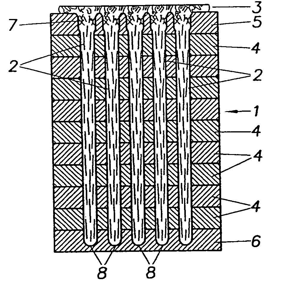
high pressure, the recommended bristle diameters of unoriented molecular structures are between 1.6 and 2.2 mm in the region of the thinner cross-section and between 11 and 12 mm in the region of the thicker cross-section (column 5, lines 43 to 48 and column, lines 32 to 42). Support structures of the same molten polymer mass are formed on the injection side of the bristles, for mounting the injection-molded bristles to a bristle support, and interconnect several bristles, if required.
[0018]The
technical literature also teaches (Ehrenstein: Eingenverstärkung von Thermoplasten im Schmelze-Deformationsprozeβ in the German
magazine “Die Angewandte Makromolekulare Chemie” 175 (1990), pages 187 to 203) that for polyamides, only 3% and 6% and for
polyethylene only 33% and 5.5% of the theoretical mechanical values for the modulus of elasticity [N / mm2] and tensile strength [N / mm2] respectively are obtained through
extrusion and injection molding methods, wherein for injection-molded components, the tension-
free state (molecular balled structure) is preferred.
[0019]It is the underlying object of the invention to produce bristles through injecting molding whose bending behavior and bend
recovery is superior to that of extruded bristles, and which permits maximum attainment of the theoretical values of the modulus of elasticity and tensile strength to produce bristles of high quality through a large length range with relatively small cross-sections for simplified production of bristle geometries and bristle arrangements adjusted to the requirements of the final product such as brushes or paint brushes. The invention also concerns a device, which is suitable for carrying out the method.SUMMARY OF THE INVENTION
[0020]Departing from the known injection molding method, wherein the molten polymer mass is injected under pressure into a bristle-molding channel of predetermined length and predetermined cross-sectional shape along this length, and the channel is vented during injection molding, this object is achieved in that the magnitude of the
injection pressure is adjusted in dependence on the cross-sectional shape of the bristle-molding channel such that a
shear flow of the molten polymer mass is generated with high core speed in the center of the molten polymer mass flow and large shearing effect due to wall friction under distinct longitudinal orientation of the polymer molecules, at least in the region of the molten polymer mass close to the wall, which is maintained along the channel, wherein the channel is simultaneously vented along its length to support maintenance of the shear flow.
[0021]The invention Is based on the realization that the bending behavior of a monofilament can be primarily increased through generation and maintenance of a molecular orientation which has previously not been realized in injection molding of bristles, brushes and paint brushes. The molecular structure in a molten polymer mass flow can only be substantially influenced using sufficiently narrow cross-sections and melt flow forced to a speed profile having strong shearing effects to deform and stretch the energetically most favorable tension-free balled structure. For this reason, in accordance with the invention, the
injection pressure is set to a sufficiently high level that a steep flow profile forms in the bristle-molding channels which is characterized by a high core speed in the center of the flow and large shearing effect in its
edge region due to the wall friction of the molten polymer mass on the channel wall, wherein the shearing forces due to wall friction are larger the higher the speed difference between neighboring flow
layers. A flow profile of this type with high core speed moreover ensures perfect filling of the mold of the bristle-molding channel even for the narrowest of cross-sections (small bristle
diameter) and large channel length (bristle length).
[0022]The speed profile can be set in dependence on the predetermined cross-sectional shape along the length of the bristle-molding channel through a correspondingly high, optionally variable injection pressure. The polymer molecules are thereby oriented longitudinally close to the channel wall and, to a reduced degree, within the entire melt flow, wherein the magnitude of the core speed moreover prevents premature solidification of the molten mass, even for small cross-sections and large lengths.
