Control for dual stepper motors

a stepper motor and control technology, applied in ventilation systems, lighting and heating apparatus, heating types, etc., can solve the problems of increasing the amount of energy consumed by the unit, increasing the power supply section of the unit, and increasing the unit cost, so as to increase the discharge flow pattern of the air conditioning unit without increasing the amount of energy consumed. , the effect of increasing the size of the uni

Active Publication Date: 2007-11-13
CARRIER CORP
View PDF9 Cites 1 Cited by
  • Summary
  • Abstract
  • Description
  • Claims
  • Application Information

AI Technical Summary

Benefits of technology

[0006]It is a further object of the present invention to expand the discharge air flow pattern of an air conditioning unit without considerably increasing the size of the unit.
[0007]A still further object of the present invention is to increase the discharge flow pattern of an air conditioning unit without increasing the amount of energy that is consumed.
[0008]These and other objects of the present invention are attained by air handling unit that includes a series horizontally disposed louvers and a series of vertically disposed louvers that are movably mounted in the discharge air flow of the unit. A first multi-phase stepper motor is arranged to move the horizontal louvers a given number of steps in one direction and a given number of steps in the opposite direction. A second multi-phase stepper motor is arranged to similarly move the vertical louvers a given number of steps in one direction and a given number steps in the opposite direction. A single transformer provides power to both of the stepper motors. The unit controller is programmed to apply power alternately to the two stepper motors during each motor phase to step each motor in equal increment without any considerable loss of torque or increase in power consumption.

Problems solved by technology

This approach resulted in the need for considerably more space in the power supply section of the unit and an increase in the unit cost as well as an increase in the amount of energy consumed by the unit.

Method used


Image

  • Control for dual stepper motors
  • Control for dual stepper motors
  • Control for dual stepper motors

Examples


Embodiment Construction

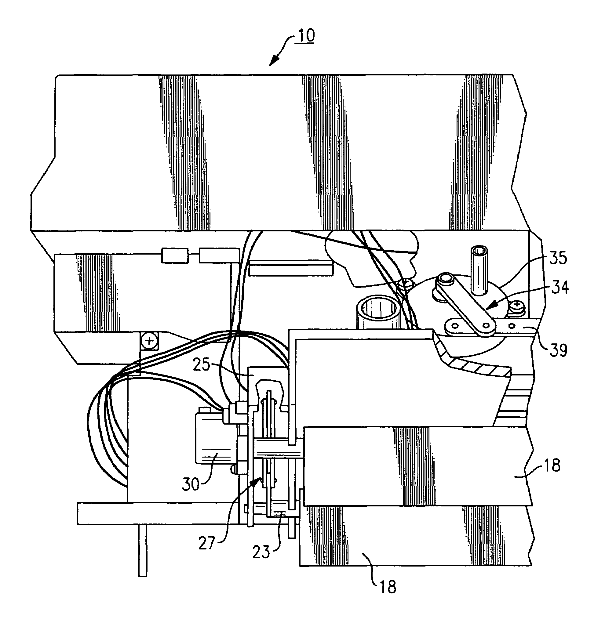
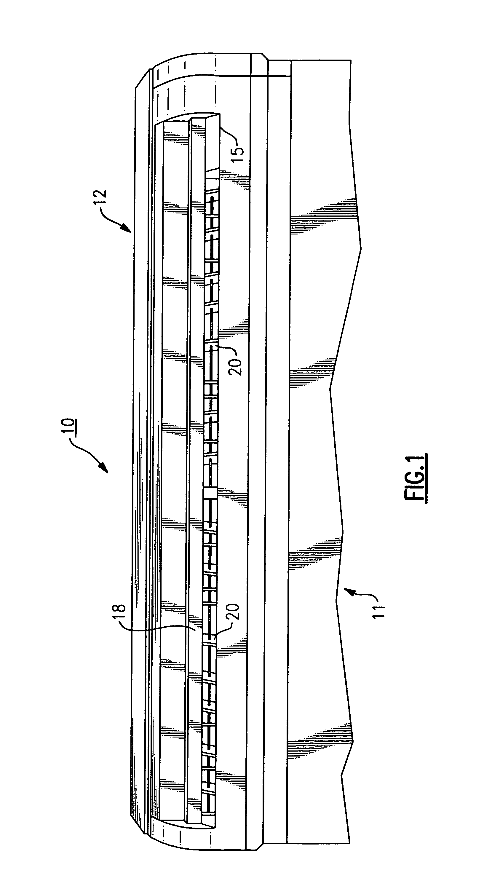
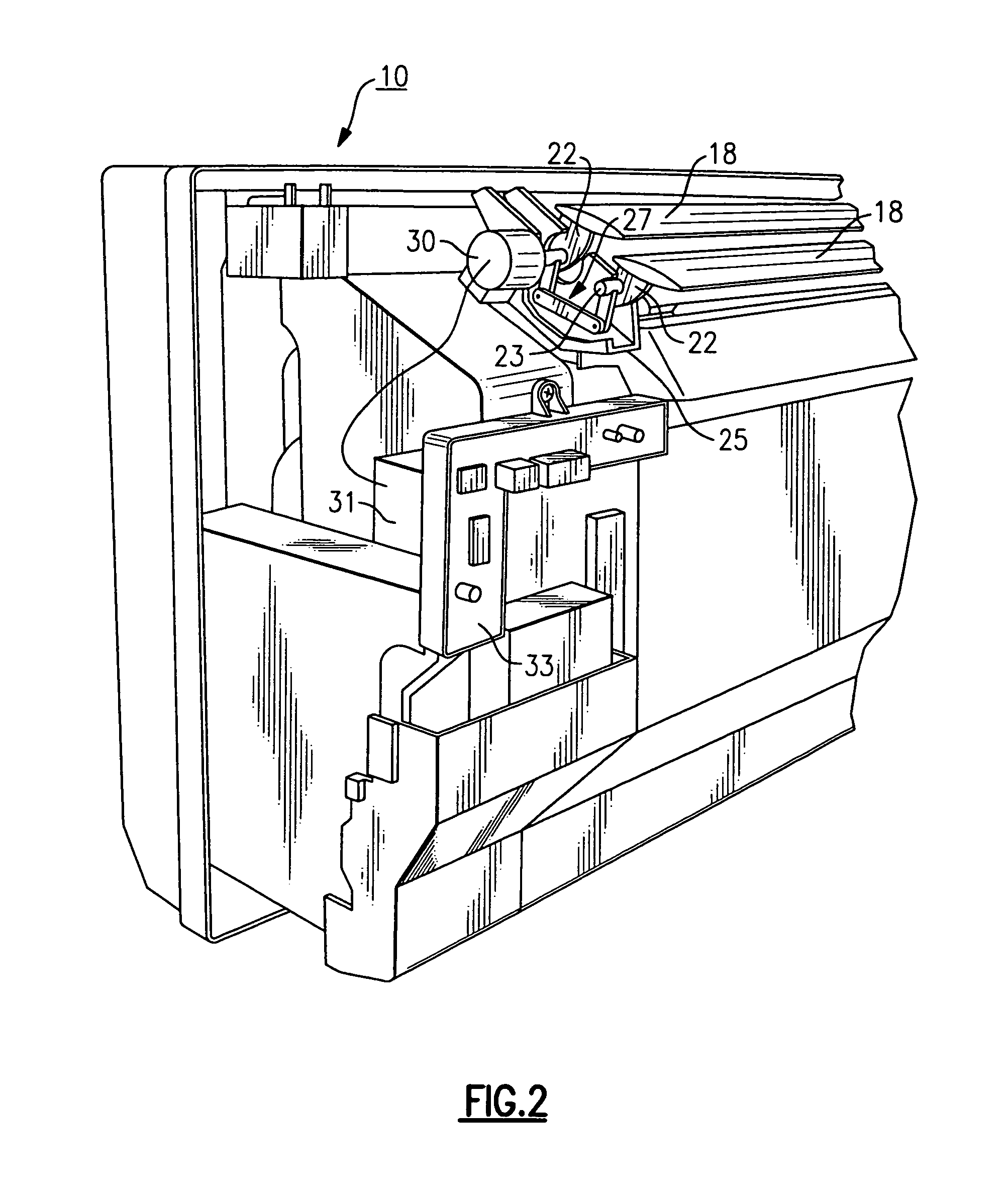
[0016]Referring initially to FIG. 1, there is illustrated an air conditioning unit, generally referenced 10, that embodies the teachings of the present invention. The unit includes an enclosed cabinet having a removable top cover 12 in which an elongated opening 15 is provided through which a flow of condition air is discharged from the unit into the surrounding ambient. Although the present invention will be described with specific reference to an air conditioning unit, it should be evident from the disclosure below that the invention has broader application and may be used in any suitable air handling system in which air is exchanged between the system and the surrounding ambient. A pair of horizontally disposed louvers 18 are mounted within the discharge opening for deflecting the discharge airflow of conditioned air in a vertical direction. A series of vertically disposed louvers 20 are mounted adjacent to and behind the horizontal louvers within the discharge flow for deflectin...


PUM


Abstract

In an air handling unit for discharging a flow of air into the surrounding ambient, having a series of horizontal louvers and a series of vertical louvers mounted in the discharge flow. A first multi-phase stepper motor is arranged to step the horizontal louvers to deflect the air flow in a vertical direction and a second multi-phase stepper motor is arranged to step vertical louvers to deflect the flow in a transverse direction. A controller is programmed to alternately apply power from a single power source to each of the motors during each phase to step each motor in equal increments during each phase.

Description

FIELD OF THE INVENTION[0001]This invention relates to an air handling system and, in particular, to a louver assembly for deflecting the flow of air that is being exchanged between the system and the surrounding ambient to expand the flow pattern of the discharged air.BACKGROUND OF THE INVENTION[0002]In many air handling systems and in particular, air conditioning systems, the conservation of both space and energy is of primary concern. Most room air conditioning units in use today are mounted in compact cabinets with the conditioned air being discharged from the unit through an elongated opening that extends horizontally across the face of the unit cabinet.[0003]Typically, a series of parallelly aligned horizontal louvers are mounted in the discharge opening of the cabinet and a series of vertically aligned louvers are mounted behind the horizontal louvers. The horizontal louvers are connected to a programmed stepper motor by a rocker arm arrangement. The motor is programmed throug...

Claims


Application Information

Patent Timeline
Patent Type & Authority Patents(United States)
IPC IPC(8): F24F13/15
CPCF24F1/0011F24F13/06F24F2013/1433F24F2001/0048F24F1/0057F24F13/1426F24F2221/17
Inventor DOLAN, ROBERT P.LYNN, DOUGLAS C.
Owner CARRIER CORP
Why Eureka
Try Eureka