
Method for increasing accuracy of measurement of mean polarization mode dispersion

a technology of mean polarization mode and measurement method, which is applied in the direction of instruments, optical apparatus testing, structural/machine measurement, etc., can solve the problem of significant broadening of optical pulse propagation along long lengths of fiber, and achieve the effect of improving the accuracy of measuring a differential group delay (dgd)

Inactive Publication Date: 2007-11-06
FICO MIRRORS SA +1
View PDF12 Cites 43 Cited by
  • Summary
  • Abstract
  • Description
  • Claims
  • Application Information

AI Technical Summary

Benefits of technology

"The present invention provides methods for improving the accuracy of measuring the differential group delay in optical fibers. The methods involve measuring the root mean squared difference in the polarization mode dispersion of a source at a finite spectral bandwidth and applying a systematic correction factor to account for the finite spectral bandwidth of the source. The methods can be used with time-domain or frequency-domain techniques and can be applied to measurements taken using a polarimeter or other apparatus. The methods can be used to measure the mean differential group delay in a single optical fiber link or an entire optical fiber route. The invention also provides a method for measuring the mean square differential group delay of at least one length of optical fiber."

Problems solved by technology

Consequently, components of an optical signal that differ in polarization will propagate at different velocities, resulting in a differential group delay (DGD) between the components, and causing significant broadening of the optical pulses propagating along long lengths of fiber.

Method used


Image

  • Method for increasing accuracy of measurement of mean polarization mode dispersion
  • Method for increasing accuracy of measurement of mean polarization mode dispersion
  • Method for increasing accuracy of measurement of mean polarization mode dispersion

Examples


Embodiment Construction

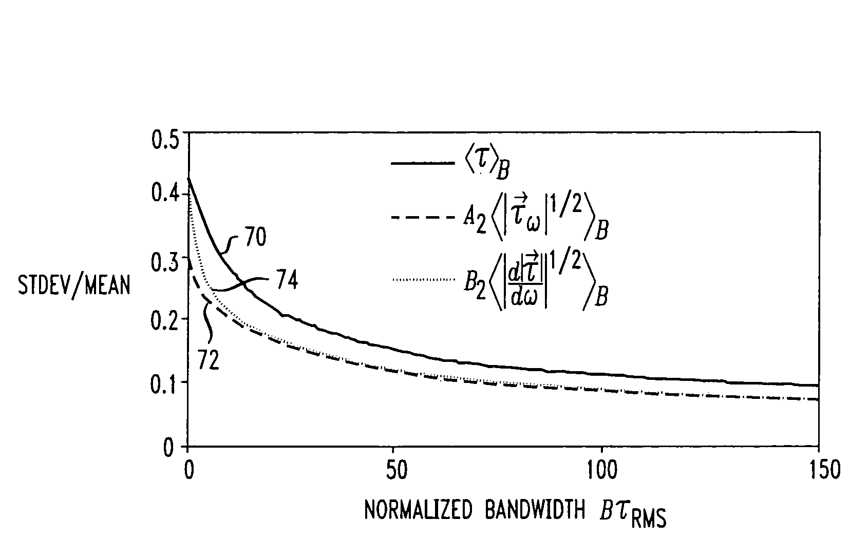
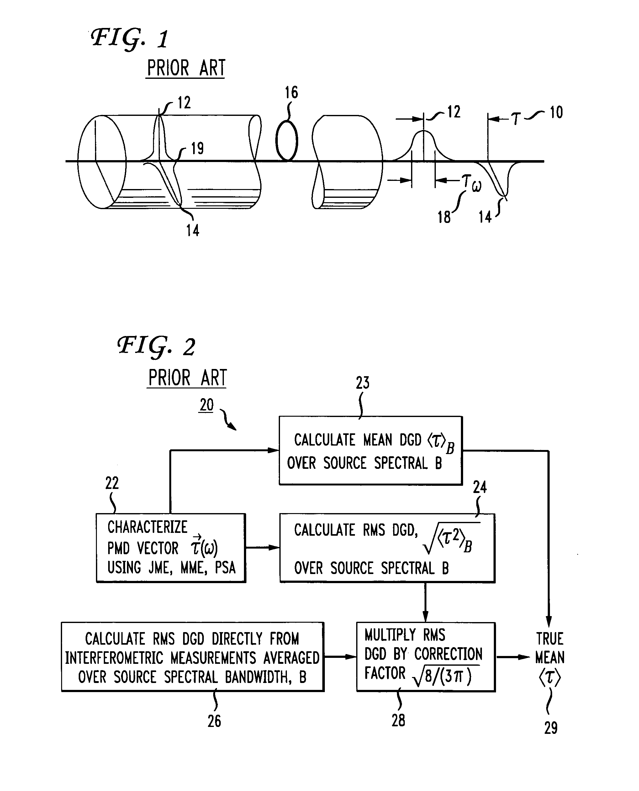
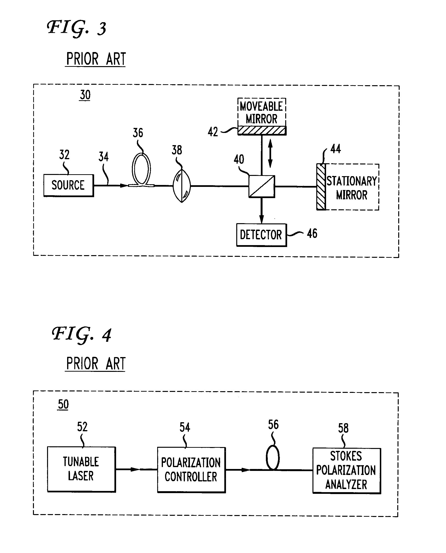
[0045]The present invention relates to improving the accuracy of calculating a true mean differential group delay (DGD) or a true mean-square DGD τ from a measurement of polarization mode dispersion (PMD). The present invention provides a method for correcting a systematic error in a conventional conversion of measured mean-square DGD measurements to a true mean DGD τ. The systematic error stems from the use of a measurement source of a finite bandwidth B, and from the conventional conversion applied to measured root mean square DGD √{square root over (τ2B)} to obtain an estimate of true mean DGD τ. By incorporating improved averaging techniques to the measured root mean square DGD √{square root over (τ2B)} obtained with conventional PMD measurement apparatus, the present invention offers improved resolution in true mean τ or true mean-square DGD τ2 measurements.

[0046]The present invention also provides a method to improve accuracy in measurements of the true mean DGD τ of optical f...


PUM

PropertyMeasurementUnit
lengthaaaaaaaaaa
polarization mode dispersion measurementaaaaaaaaaa
time-aaaaaaaaaa

Abstract

The present invention provides a method for increasing the accuracy of measurement of mean differential group delay (DGD) from the polarization mode dispersion (PMD) in optical fiber. The method includes a systematic correction to mean-square DGD measured with any conventional mean to minimize systematic error caused by finite source bandwidth. The method further includes a systematic correction to the measurement of mean DGD and mean square DGD from statistics of the second-order PMD (SOPMD) obtained with frequency domain PMD-measuring apparatus. The probability density function (PDF) of either the vector or scalar SOPMD is applied, depending on which quantity is measured. The systematic correction is made to minimize the systematic error in estimating mean DGD, caused by finite source bandwidth, to achieve a two-fold reduction of the measurement variance equivalent to doubling the source bandwidth.

Description

FIELD OF THE INVENTION[0001]The invention relates to the field of high-speed optical telecommunication systems, and more particularly to a method for increasing the accuracy of the measurement of mean polarization mode dispersion in optical fiber.BACKGROUND OF THE INVENTION[0002]The optical waveguides or fibers used to transmit signals in optical telecommunication systems are characterized, in part, by the vector property of polarization mode dispersion (PMD). Polarization mode dispersion occurs as a result of birefringence in the fiber, which may be caused by physical asymmetry in the fiber construction itself, or by stress, strain, or other external forces imposed on the fiber. In addition, random polarization coupling can occur, giving rise to a time-varying statistical factor. Optical fibers display an anisotropy in the refractive index, which will vary as a function of position and time. Consequently, components of an optical signal that differ in polarization will propagate at...

Claims


Application Information

Patent Timeline
Patent Type & Authority Patents(United States)
IPC IPC(8): G01N21/00G01M11/02G01M11/00H04B10/18
CPCG01M11/331H04B10/2569G01M11/336
Inventor BORODITSKY, MIKHAILBRODSKY, MIKHAILFRIGO, NICHOLAS J.MAGILL, PETER
Owner FICO MIRRORS SA
Learn More