
Joint for fluid transport lines for medical use

a fluid transport line and fluid technology, applied in the direction of turning machine accessories, drilling pipes, chucks, etc., can solve the problems of distortions that might be wrongly interpreted, interference problems in the ecg, distortions in the ecg, etc., to eliminate any risks involving the patient's well-being, simple and economical manufacturing, and the effect of simple and economical

Active Publication Date: 2007-11-06
GAMBRO LUNDIA AB
View PDF30 Cites 49 Cited by
  • Summary
  • Abstract
  • Description
  • Claims
  • Application Information

AI Technical Summary

Benefits of technology

The solution effectively reduces or eliminates ECG artefacts caused by peristaltic pumps, maintaining electrical insulation and bio-compatibility, and is simple and economical to manufacture and integrate into existing systems.

Problems solved by technology

One of the problems encountered during a dialysis treatment, especially in cases of intensive therapy, is that the rotation of the peristaltic pumps, in particular the blood pump, causes disturbances (known as artefacts) in the ECG.
This interference problem in the ECG is found both in complex apparatus, such as a dialysis machine for intensive treatment, as well as in more simple apparatus, such as an infusion device comprising an infusion line with a peristaltic pump.
The alteration in the ECG recording can lead to an indistinguishable tracing, or can cause distortions that might be wrongly interpreted and confused with signs of cardiac anomalies.

Method used


Image

  • Joint for fluid transport lines for medical use
  • Joint for fluid transport lines for medical use
  • Joint for fluid transport lines for medical use

Examples


first embodiment

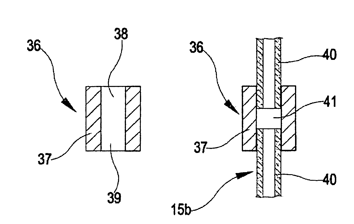
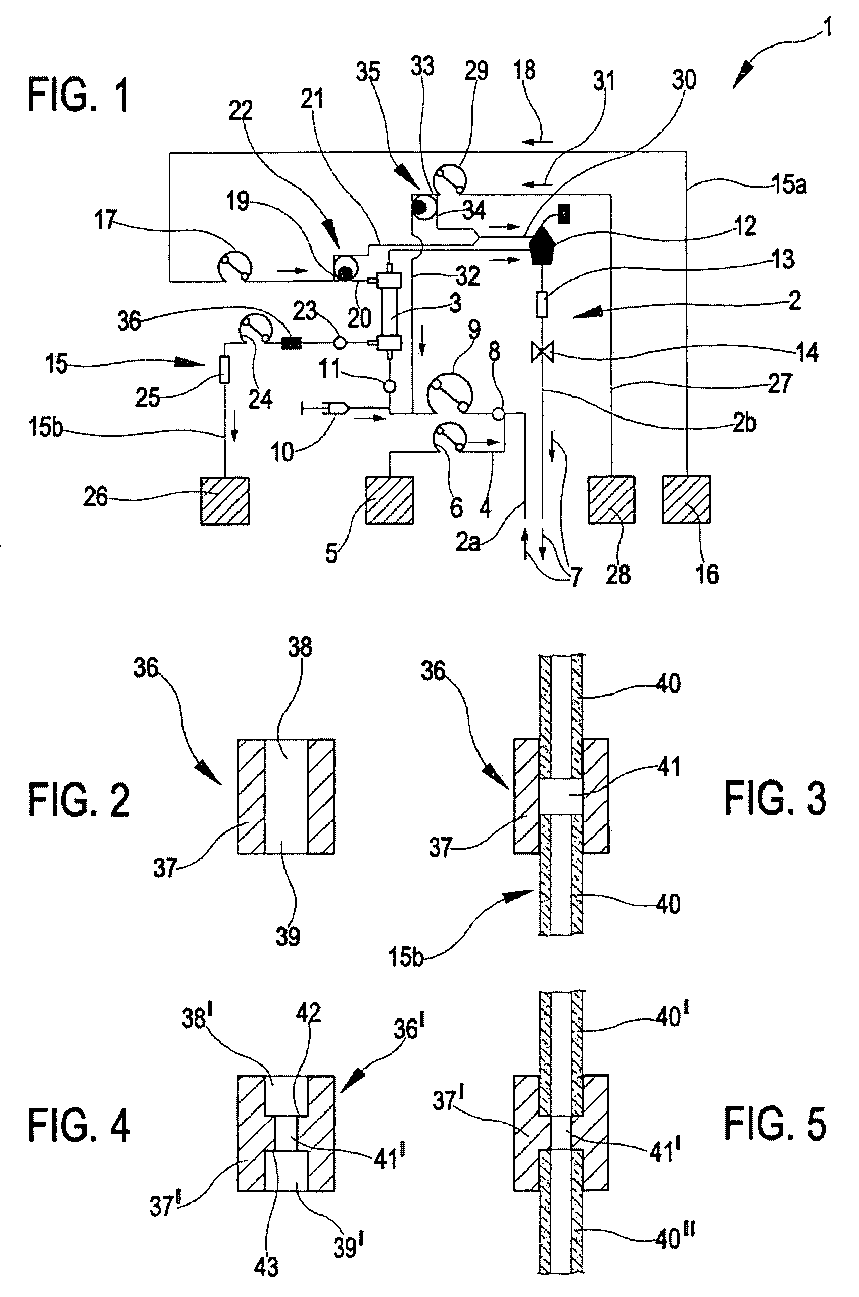
[0081]The joint 36 is illustrated, in a first embodiment, in FIG. 2. In FIG. 3, the joint 36 is coupled to the drainage line 15b.

[0082]The joint 36 comprises a tubular body 37, substantially a sleeve-shape, having a cylindrical lateral external side and at two opposite ends two connecting zones 38 and 39, each of which, has a cylindrical internal lateral surface for connecting with an end zone of a usual tubular element 40 of a fluid transport line for medical use. The connection gives continuity to fluid passage.

[0083]Each tubular element 40 is a flexible elongate body, with elastically deformable walls, made of a dielectric plastic material, generally a thermoplastic resin, such as for example bio-compatible plasticized PVC.

[0084]The joint 36 is made in a single piece with a relatively small longitudinal extension having more rigid walls than the tubular elements 40.

[0085]In the illustrated example the joint 36 is made of a composite material including a mix of plastic material, ...

second embodiment

[0099]In a second embodiment, illustrated in FIG. 4, the conductive joint 36′ is constituted by a tubular body 37′, made in a single piece, which internally comprises at least one first axial stop element 42, operatively associated to an end zone of a first tubular element 40′, for limiting an axial insertion of the first tubular element within the tubular body.

[0100]In the illustrated embodiment, the tubular body 37′ internally comprises a second axial stop element 43, axially distanced from the first axial stop element 42, and operatively associated to an end zone of the second tubular element 40″, for limiting an axial insertion of the second tubular element inside the tubular body 37′, in an opposite direction with respect to the axial insertion of the first tubular element 40′.

[0101]The tubular body 37′ has an intermediate zone 41′ comprised axially between the two end connecting zones 38′ and 39′, the internal diameter of which is smaller than the internal diameter of the conn...


PUM


Abstract

The joint (36) comprises a tubular body (37) having two connecting zones (38, 39) each connected by an end to a tubular element (40) of a fluid transport line, giving continuity to passage of fluid. The tubular body is made of a mixture of an electrically-conductive material such as PVC, with carbon black to give it electrical conductivity. The joint has an internal surface (41) which is destined to come into contact with the transported fluid, and an external surface which is destined to have a grounded galvanic contact. The joint is inserted in the discharge fluid drainage line of a dialyzer filter, in an apparatus for intensive treatment of acute renal insufficiency, for eliminating ECG artefacts due to functioning of peristaltic pumps in the apparatus.

Description

CROSS REFERENCE TO RELATED APPLICATIONS[0001]This application claims the priority of Italian Application No. M02003 A 000165, filed on Jun. 4, 2003, and claims the benefit of U.S. Provisional Application No. 60 / 511,327, filed on Oct. 16, 2003.BACKGROUND OF THE INVENTION [0002]The invention relates to a joint for fluid transport lines for medical use, to a fluid transport line comprising the joint, to an infusion device comprising the line, to a circuit for extracorporeal blood treatment comprising the line, to a machine for extracorporeal blood treatment which is operatively associable to the circuit, and to an apparatus for extracorporeal treatment of blood comprising the machine and the circuit.[0003]Specifically, though not exclusively, the invention can be usefully applied in the field of intensive treatment of acute renal insufficiency.[0004]In the prior art, renal insufficiency, both chronic and acute, is treated by extracorporeal dialytic treatment, in which blood is removed ...

Claims


Application Information

Patent Timeline
Patent Type & Authority Patents(United States)
IPC IPC(8): A61M37/00A61M39/10A61M1/16A61M5/14
CPCA61M5/1418A61M39/10A61M1/16Y10T403/23A61M2205/0233A61M2230/04
Inventor BARALDI, VINCENZODELNEVO, ANNALISAMARCHESI, GIANFRANCOLIGABUE, ANDREAZACCARELLI, MASSIMO
Owner GAMBRO LUNDIA AB
Learn More