
Impact device with a rotable control valve

a control valve and impact device technology, applied in the direction of percussive tools, manufacturing tools, portable drilling machines, etc., can solve the problems of increasing the rising speed and the magnitude of the stress pulse, and achieve the effect of increasing the rising speed and the magnitude, reducing the stress pulse, and increasing the release speed

Inactive Publication Date: 2007-11-06
SANDVIK MINING & CONSTR OY
View PDF16 Cites 16 Cited by
  • Summary
  • Abstract
  • Description
  • Claims
  • Application Information

AI Technical Summary

Benefits of technology

The present invention relates to an impact device and control valve for efficient generation of a stress pulse. The invention is characterized by the use of a rotating control valve with parallel control channels that open and close the connection between the hydraulic fluid space and the discharge channel, allowing for controlled hydraulic fluid flow to and from the stress element. The speed of rotation of the control valve is adjusted to control the impact frequency, and spindle-like auxiliary valves are used to increase the rising speed and magnitude of the stress pulse. The use of several parallel control channels allows for efficient implementation of the rapid pressure drop required for a stress pulse, and sliding seals adjustable with hydraulic medium reduce friction and wear. The technical effects of the invention include improved efficiency and control of stress pulse generation.

Problems solved by technology

The use of spindle-like auxiliary valves allows particularly the release speed to be raised still higher, resulting in an increase in the rising speed and the magnitude of the stress pulse.

Method used


Image

  • Impact device with a rotable control valve
  • Impact device with a rotable control valve
  • Impact device with a rotable control valve

Examples


Embodiment Construction

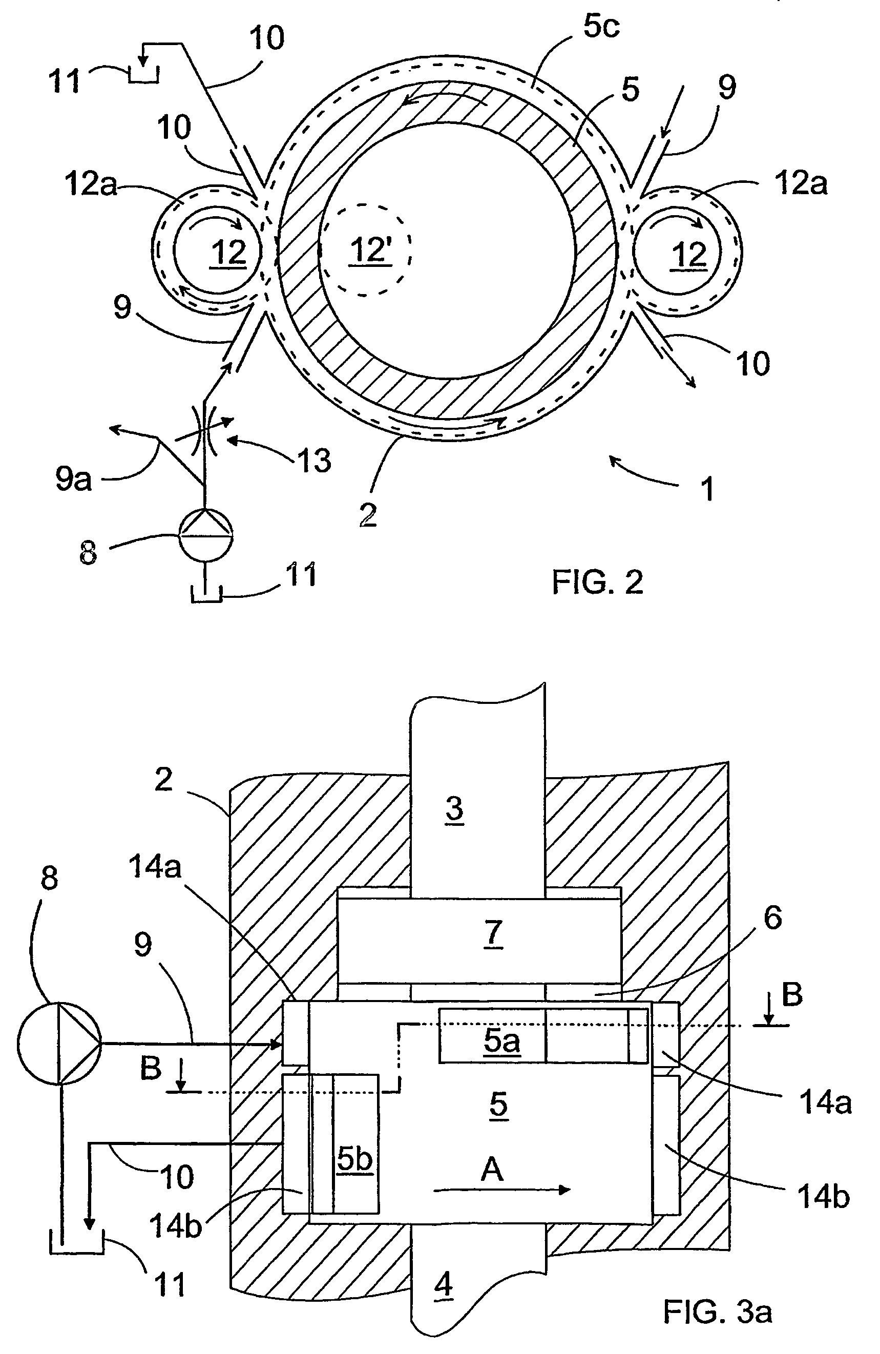
[0018]FIG. 1a is a schematic sectional view of an impact device 1 according to the invention, comprising a frame 2 and a stress element 3 therein. The stress element is located coaxially with a tool 4, one end of the stress element 3 being supported to the frame 2 during impacts and, correspondingly, the opposite end to the end of the tool 4 or a shank fastened thereto and known per se. Coaxially with the stress element 3 and, therefore also with the tool 4, is provided a rotatingly installed control valve 5, which is rotated around its axis with a suitable rotating mechanism or turned rotatingly back and forth. One such rotating mechanism is shown in FIG. 2. FIG. 1 further shows a first hydraulic fluid space 6 in the frame 2 of the impact device, and a transmission member, for instance a transmission piston 7 in the hydraulic fluid space, which are used to stress the stress element 3 and, correspondingly, released by means of the rotating valve 5. The transmission piston 7 comprise...


PUM

PropertyMeasurementUnit
stressaaaaaaaaaa
pressureaaaaaaaaaa
timeaaaaaaaaaa

Abstract

An impact device includes a frame to which a tool is connectible, and a stress element that is supported on the frame and disposed between the frame and the tool. A hydraulic control system leads pressurized hydraulic fluid into and out of a hydraulic fluid space such that the stress element causes a stress pulse in the tool. The hydraulic control system includes a rotatingly installed control valve that has control openings for intermittently leading the hydraulic fluid out from the hydraulic fluid space.

Description

CROSS-REFERENCES TO RELATED APPLICATIONS[0001]The present application is a continuation application of International Application No. PCT / FI2004 / 000082 filed Feb. 23, 2004 and published in English as WO 2004 / 073933 A1 on Sep. 2, 2004, which application claims the benefit of priority to Finnish Application No. 20030261 filed Feb. 21, 2003.BACKGROUND OF THE INVENTION[0002]The invention relates to an impact device for generating a stress pulse in a tool, the impact device comprising a frame to which the tool is connectible, and between the frame and the tool a transmission member, such as a transmission piston, the tool being in contact with the tool-side end of the transmission member either directly or indirectly at least part of the time during the generation of the stress pulse, means for generating a force between the frame and the transmission member such that the force tends to push the transmission member towards the tool, and a first hydraulic fluid space on the tool-side relat...

Claims


Application Information

Patent Timeline
Patent Type & Authority Patents(United States)
IPC IPC(8): B25D9/00B25D9/22
CPCB25D9/22B23B2251/02B25D2209/005E21B1/28
Inventor KESKINIVA, MARKKUMAKI, JORMAESKO, MAURIAHOLA, ERKKI
Owner SANDVIK MINING & CONSTR OY
Learn More