
Vehicle impact attenuator

a technology of impact attenuator and pipe-like member, which is applied in the direction of roadway safety arrangements, roads, construction, etc., can solve the problems of secondary accidents, damage to colliding vehicles, and inability to effectively inhibit damage to occupants and vehicles, so as to achieve the effect of optimizing the impact absorption capacity of the pipe-like member

Inactive Publication Date: 2007-10-30
OSAKA RES INST OF IND SCI & TECH +2
View PDF26 Cites 13 Cited by
  • Summary
  • Abstract
  • Description
  • Claims
  • Application Information

AI Technical Summary

Benefits of technology

The present invention provides a vehicle impact attenuator that can be installed in a narrow space with limited space, effectively mitigates the impact received by a colliding vehicle, and immediately stop the vehicle. The attenuator comprises a shock absorber, a support, and a holding portion that holds the support in a vertical position in an installation area. The support is a pipe-like or rod-like member that has cuts or a burying hole formed in the installation area to accommodate the lower part of the support. The holding portion has a release portion that fractures upon application of a load equal to or exceeding a set value to release the support. The attenuator can be installed at a low cost.

Problems solved by technology

However, with these devices, colliding vehicles still receive a large impact, and the damage to the occupants and vehicles cannot be effectively inhibited.
Further, these devices are likely to greatly damage the colliding vehicles and the scattered fragments are liable to cause secondary accidents.
However, this type of devices also pose a problem in that a vehicle receives a large impact when it collides with them while traveling at a high speed.
Further, containers knocked over by a vehicle may scatter on the road, or a colliding vehicle may not be decelerated even after knocking down the containers and may jump over the base of the containers into the opposite lane, causing secondary accidents.

Method used


Image

  • Vehicle impact attenuator
  • Vehicle impact attenuator
  • Vehicle impact attenuator

Examples


first embodiment

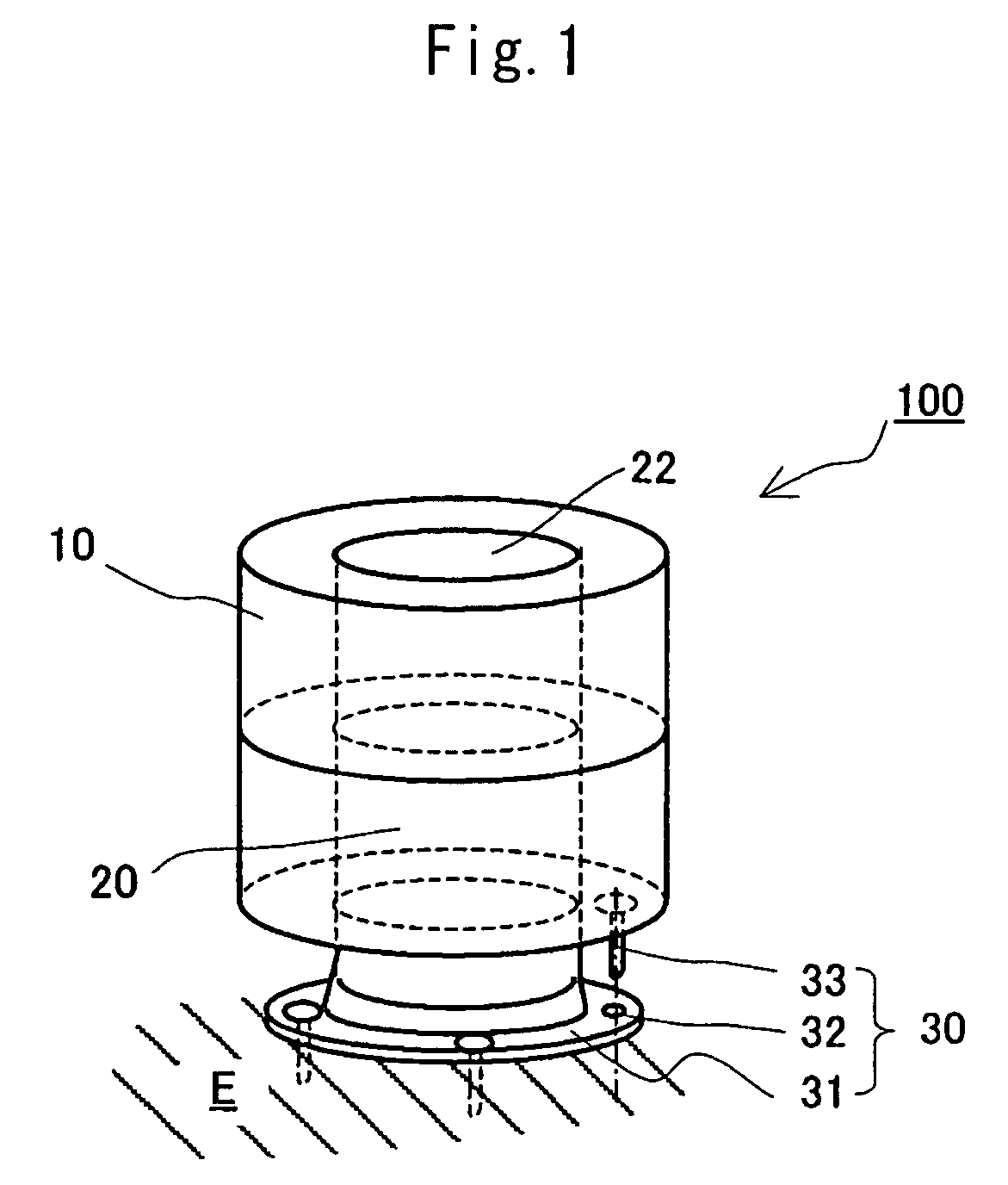
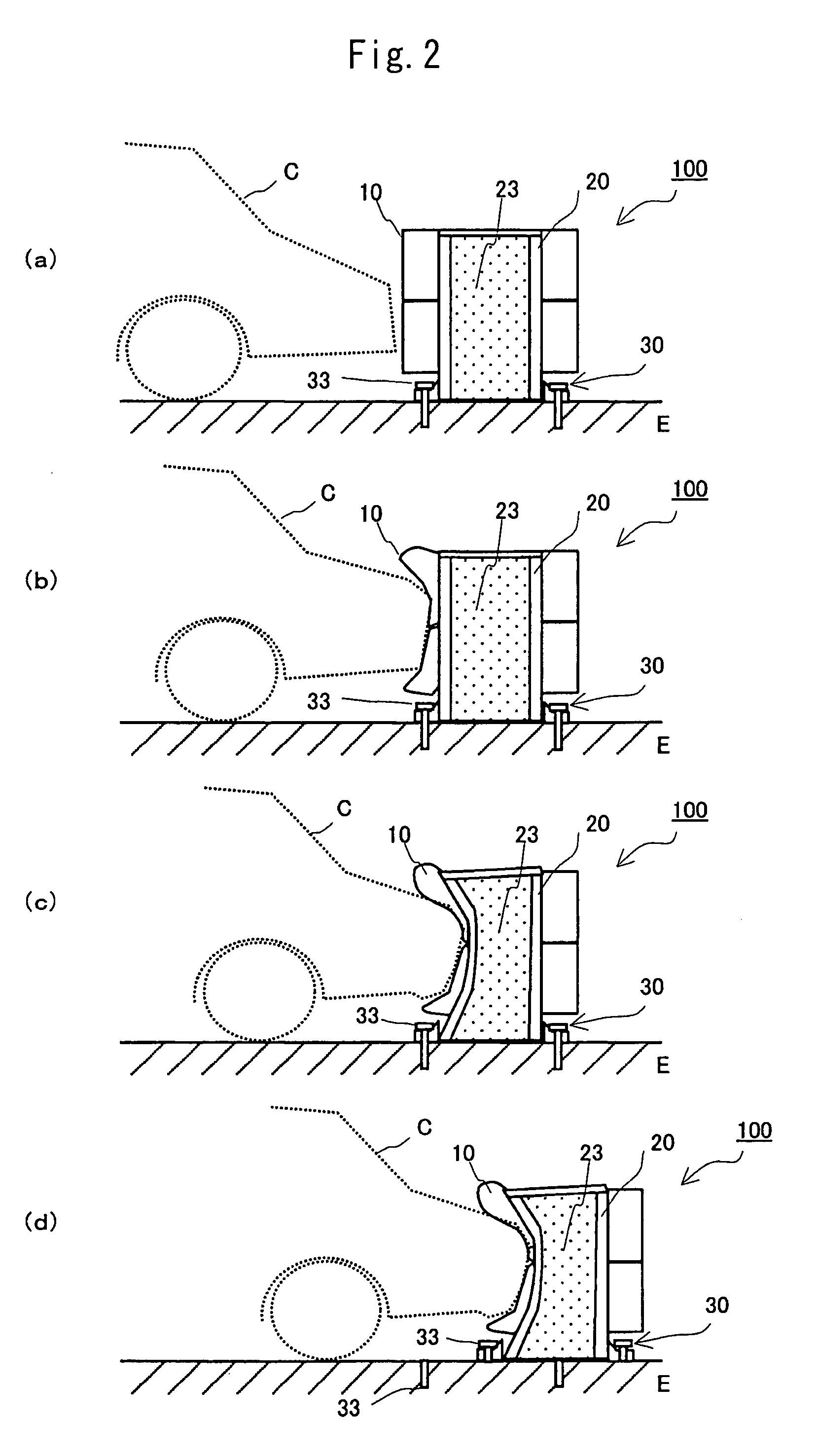
[0052]FIG. 1 is a perspective view of a vehicle impact attenuator according to a first embodiment of the present invention. FIG. 2(a) to (d) are longitudinal sectional views illustrating the deformation of the vehicle impact attenuator of FIG. 1 at the time of a vehicle collision.

[0053]As illustrated in FIG. 1, the vehicle impact attenuator 100 according to the first embodiment of the present invention comprises a shock absorber 10 that deforms upon a collision by a vehicle to thereby mitigate the impact on the vehicle, a support 20 for the shock absorber 10, and a holding portion 30 that is fixed on an installation surface E and holds the support 20 in a vertical position on the installation surface E. The holding portion 30 comprises a release portion having a breaking strength that allows the release portion to fracture upon application of a load equal to or exceeding a set value and thereby release the support 20. Further, the support 20 has a deformation strength that allows th...

second embodiment

[0069]FIG. 3 is a perspective view of a vehicle impact attenuator according to a second embodiment of the present invention. FIG. 4 is a series of longitudinal sectional views illustrating the deformation of the vehicle impact attenuator illustrated in FIG. 3 at the time of a vehicle collision.

[0070]As shown in the figures, the vehicle impact attenuator 100A according to the second embodiment of the present invention comprises a shock absorber 10A that deforms upon a collision by a vehicle to thereby mitigate the impact on the vehicle, and a support 20A for the shock absorber 10A. Like in the first embodiment, the support 20A is a pipe-like member (e.g., a cylindrical steel pipe). A continuing portion 32A formed as a lower part of the support 20A is buried in a region below the installation surface E (hereafter the installation surface E and the region below it are collectively referred to as the “installation area”), whereby the support 20A is held vertically to the installation su...

third embodiment

[0076]FIG. 5 is a perspective view illustrating a vehicle impact attenuator according to a third embodiment of the present invention. FIG. 6 is a series of longitudinal sectional views illustrating the deformation of the vehicle impact attenuator illustrated inFIG. 5 at the time of a vehicle collision.

[0077]As shown in the figures, the vehicle impact attenuator 100B according to the third embodiment of the present invention comprises a shock absorber 10B that deforms upon a collision by a vehicle to thereby mitigate the impact on the vehicle, a support 20B for the shock absorber 10B, and a holding portion 30B that is fixed on an installation surface E to hold the support 20B vertically to the installation surface E. The holding portion 30B comprises a continuing portion 32B formed as a lower part of the support 20B, and a fitting member 34B buried below the installation surface E to engage and hold the continuing portion 32B, whereby the support 20B is held in a vertical position. L...


PUM


Abstract

A vehicle impact attenuator that can be installed at low cost in a narrow installation space, immediately stop a colliding vehicle, and effectively mitigate the impact on the vehicle. The vehicle impact attenuator includes a shock absorber that deforms upon a collision by a vehicle to reduce the impact on the vehicle. A support is provided for the shock absorber and a holding portion holds the support (20A) in a vertical position in an installation area. The support has cuts made in it that upon application of a load equal to or exceeding a set value, fracture and function as a release mechanism to thereby release the support from being held in a vertical position in the installation area. The support is deformable by a load less than the set value.

Description

TECHNICAL FIELD[0001]The present invention relates to a vehicle impact attenuator to be installed on or in the vicinity of roads where vehicle collisions are liable to occur, in order to immediately stop a colliding vehicle and mitigate the impact applied to the vehicle.BACKGROUND ART[0002]Vehicle impact attenuators are installed in places where vehicle collisions tend to occur, such as the ends of median strips, road forks, and the ends of branch points for tollgates, in order to immediately stop a colliding vehicle and mitigate the impact applied to the vehicle, thereby preventing secondary accidents and reducing damage to the vehicle and its occupants.[0003]Guard fences, such as steel guardrails or guard cables, can be described as vehicle impact attenuators. However, with these devices, colliding vehicles still receive a large impact, and the damage to the occupants and vehicles cannot be effectively inhibited. Further, these devices are likely to greatly damage the colliding ve...

Claims


Application Information

Patent Timeline
Patent Type & Authority Patents(United States)
IPC IPC(8): E01F9/018E01F15/04E01F15/08E01F15/14
CPCE01F15/146E01F15/143E01F15/00E01F15/14
Inventor YAMASAKI, SEINAKAJIMA, TAKAMASA
Owner OSAKA RES INST OF IND SCI & TECH
Learn More