
Device for connecting a beam to pillars or similar supporting structural elements for erecting buildings

Inactive Publication Date: 2007-10-30
ZAMBELLI SERGIO +1
View PDF14 Cites 18 Cited by
  • Summary
  • Abstract
  • Description
  • Claims
  • Application Information

AI Technical Summary

Benefits of technology

[0014]The aim of the present invention is to provide a device for connecting a beam to pillars or similar supporting structural elements for erecting buildings, particularly multistory buildings, by means of prefabricated concrete components, that allows to reduce the height of the beam although said beam is prefabricated, without necessarily having to resort to pre-stressing of the beam, and also achieves the most uniform possible distribution of the stresses to which the beam is subjected.
[0016]Another object of the invention is to provide a device that allows to use advantageously the prefabrication method in buildings, including multistory buildings, with beams that are significantly shorter than the beams normally used in industrial buildings.

Problems solved by technology

However, in some particular sectors, the prefabrication technique has not yet been able to expand fully.
Prefabricated concrete components are in fact currently scarcely applied in this field, because prefabricated beams, in order to withstand the loads to which they are subjected by using a coupling to the pillar that consists of simple resting thereon at their ends, have an excessive vertical space occupation.
On-site building operations are able to minimize the height of the beams thanks to the fact that with this construction method there is an uninterrupted continuity between the pillar and the beam.
However, this fact entails that prefabricated beams, as mentioned, must be inevitably higher than beams built on-site.
However, this solution is advantageous with considerable spans, i.e., distances between the pillars, otherwise the resulting saving in beam height and therefore the financial saving are insignificant.
However, it should be noted that the prefabrication method allows an unequalled erection speed as well as industrial-type production and quality control; moreover, the prefabrication method allows to build regardless of weather conditions, which instead can have a severe effect on on-site building, and makes the progress of work independent of the waiting time for the concrete to cure, which greatly slows down the erection of multistory buildings with the traditional method of on-site building.
During its testing and use, the device has proved to be susceptible of improvements aimed mainly at achieving a more uniform distribution of the stresses within the beam and at introducing a new static layout.

Method used


Image

  • Device for connecting a beam to pillars or similar supporting structural elements for erecting buildings
  • Device for connecting a beam to pillars or similar supporting structural elements for erecting buildings
  • Device for connecting a beam to pillars or similar supporting structural elements for erecting buildings

Examples


Embodiment Construction

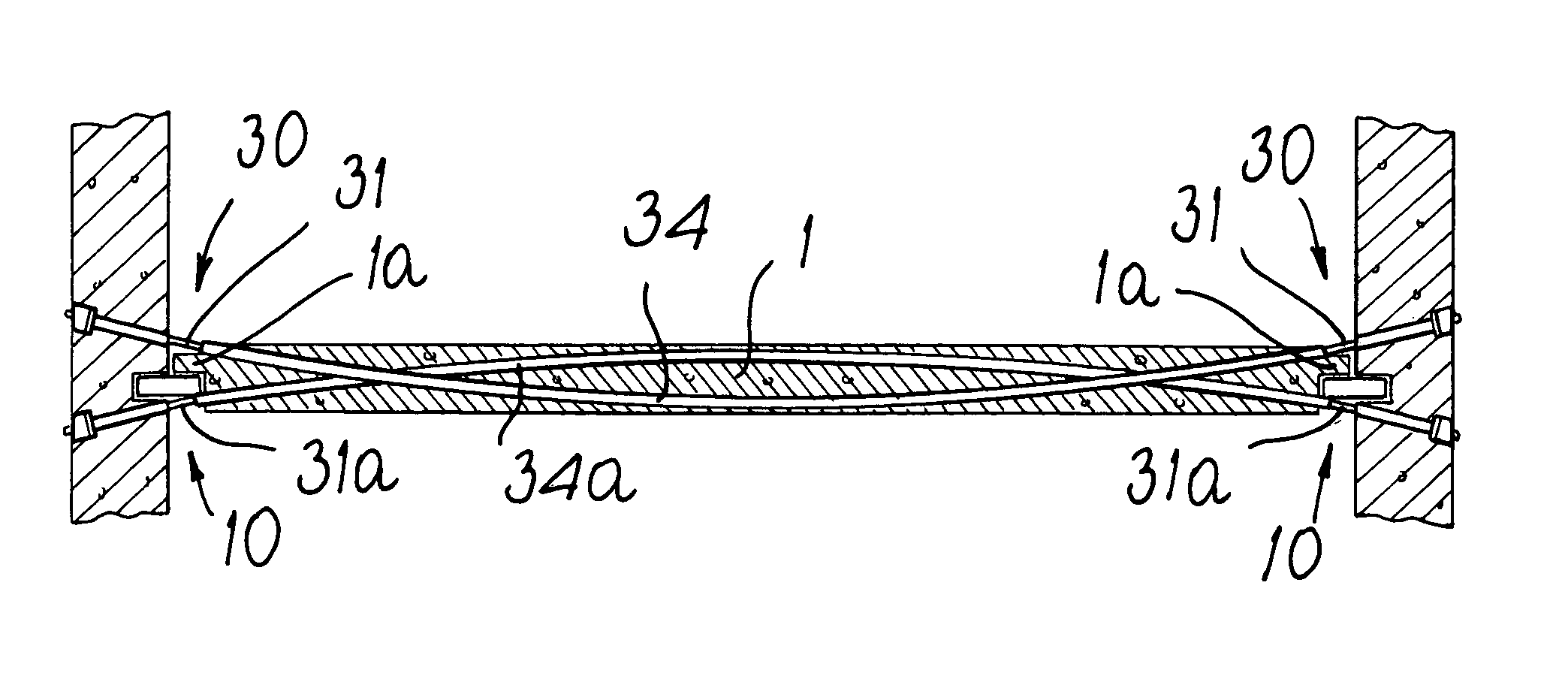
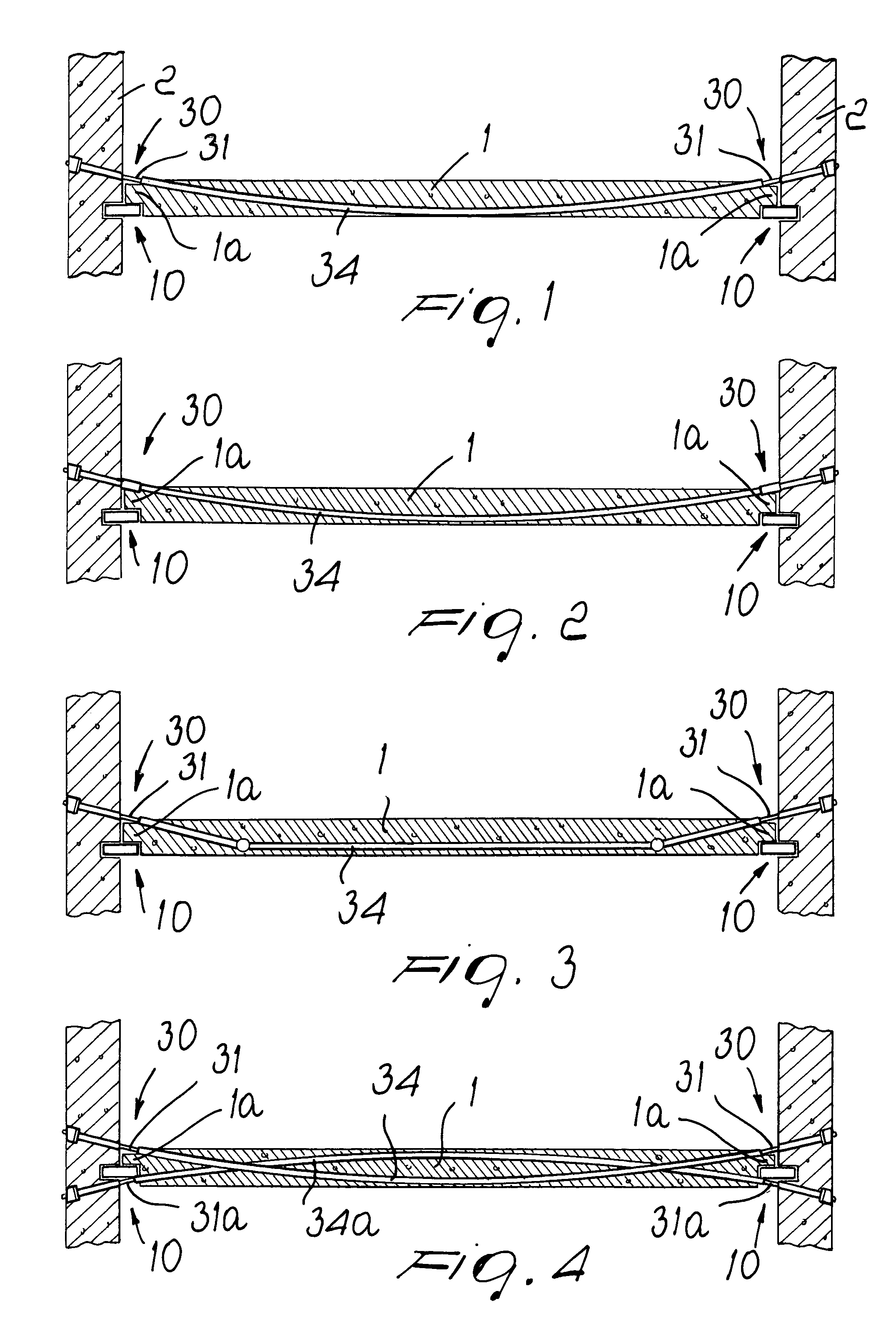
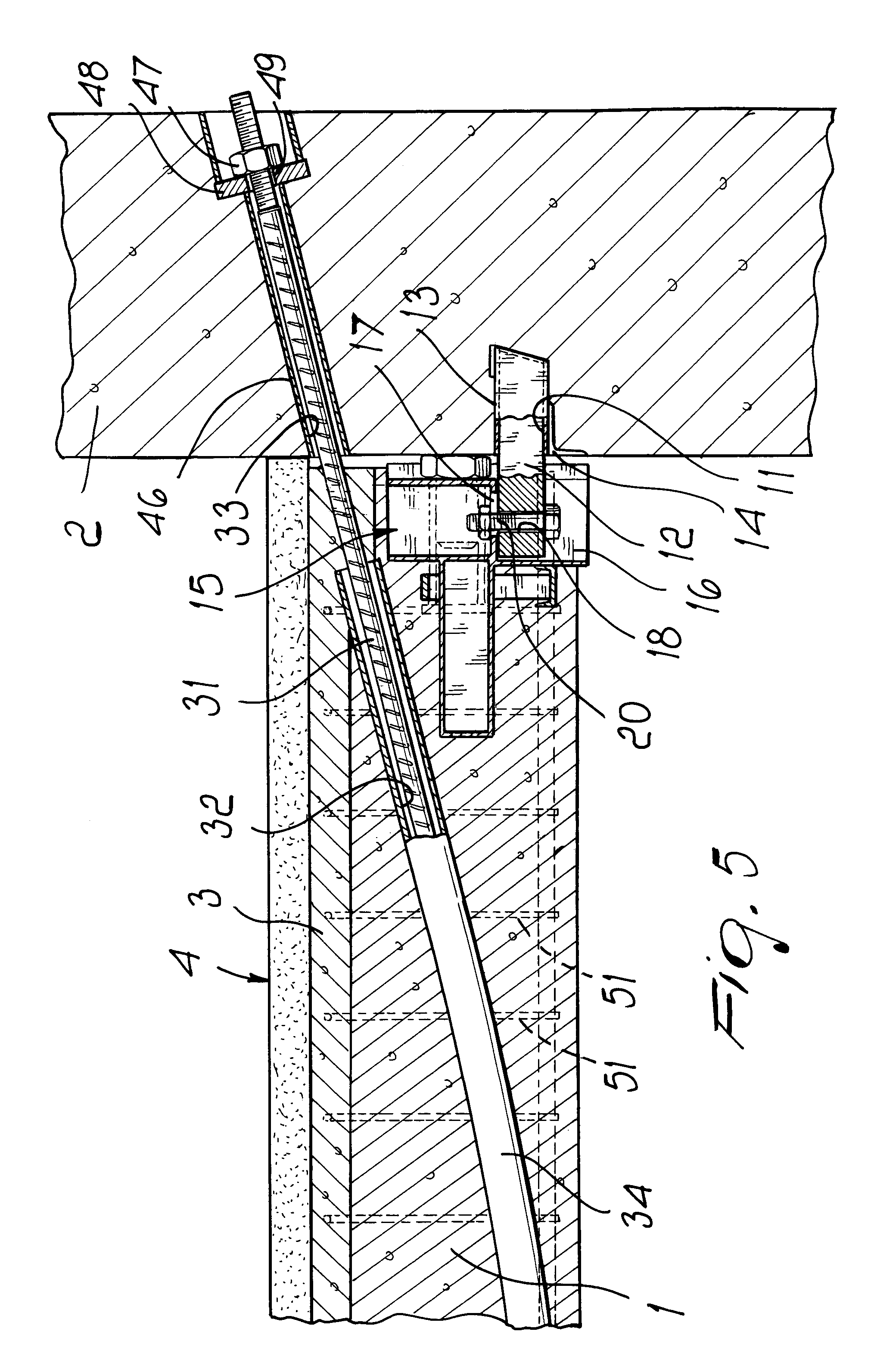
[0030]With reference to the figures, the device according to the invention, in its various embodiments, comprises first means 10 for connecting the two end regions 1a of a beam 1 to the pillars 2 that must support the beam 1, and second means 30 for connecting the beam 1 to the pillars 2.

[0031]The first connection means 10 are constituted by connection means that ensure a coupling at least of the hinge type between each one of the two longitudinal ends of the beam 1 and the corresponding pillar 2, and the second connection means 30 comprise at least one tension element 31 that passes through the beam 1 and is connected to the pillars 2 by means of its ends that protrude from the beam 1.

[0032]The device according to the invention further comprises means for tensioning to the desired extent the tension element or elements 31 so as to preload the beam 1, as will become better apparent hereinafter.

[0033]Conveniently, the regions for the passage of the tension elements 31 in the beam 1 a...


PUM


Abstract

A device for connecting a beam to pillars or similar supporting structural elements in order to erect buildings, particularly multistory buildings, by means of prefabricated concrete components, the device comprising first means for connecting two end regions of the beam to the pillars and second means for connecting the beam to the pillars, the first connection means provide a coupling at least of the hinge type between each one of the two end regions of the beam and the corresponding pillar; the second connection means comprise at least one tension element that passes through the beam and is connected to the pillars by means of the ends thereof that protrude from the beam.

Description

BACKGROUND OF THE INVENTION[0001]The present invention relates to a device for connecting a beam to pillars or similar supporting structural elements for erecting buildings, particularly multistory buildings, by means of prefabricated concrete components.[0002]As is known, the building method that uses prefabricated concrete components has, in recent years, become increasingly widespread mainly thanks to its reduced execution times compared to the traditional method of on-site building.[0003]However, in some particular sectors, the prefabrication technique has not yet been able to expand fully.[0004]One of these sectors is constituted by the erection of buildings used for office or residential purposes, particularly if they are of the multistory type.[0005]Prefabricated concrete components are in fact currently scarcely applied in this field, because prefabricated beams, in order to withstand the loads to which they are subjected by using a coupling to the pillar that consists of si...

Claims


Application Information

Patent Timeline
IPC IPC(8): E04H12/00E04B1/21E04B1/22E04B5/04E04C3/20E04C3/26E04C5/06E04C5/12
CPCE04B1/21E04B1/22E04B5/04E04C5/125E04C3/26E04C5/0645E04C3/20
Inventor ZAMBELLI, SERGIOZAMBELLI, BENITO
Owner ZAMBELLI SERGIO
Learn More