
Variable gain device

a signal processing device and variable gain technology, applied in differential amplifiers, amplifiers with semiconductor devices/discharge tubes, amplification control details, etc., can solve the problems of increased manufacturing cost and insufficient output linearity, and achieve a wider gain range and linearity. high

Inactive Publication Date: 2007-10-23
BEYOND INNOVATION TECH
View PDF3 Cites 1 Cited by
  • Summary
  • Abstract
  • Description
  • Claims
  • Application Information

AI Technical Summary

Benefits of technology

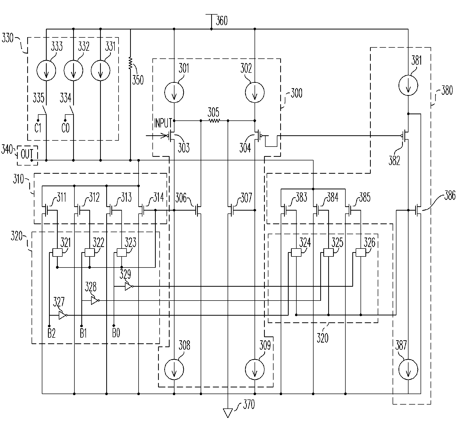
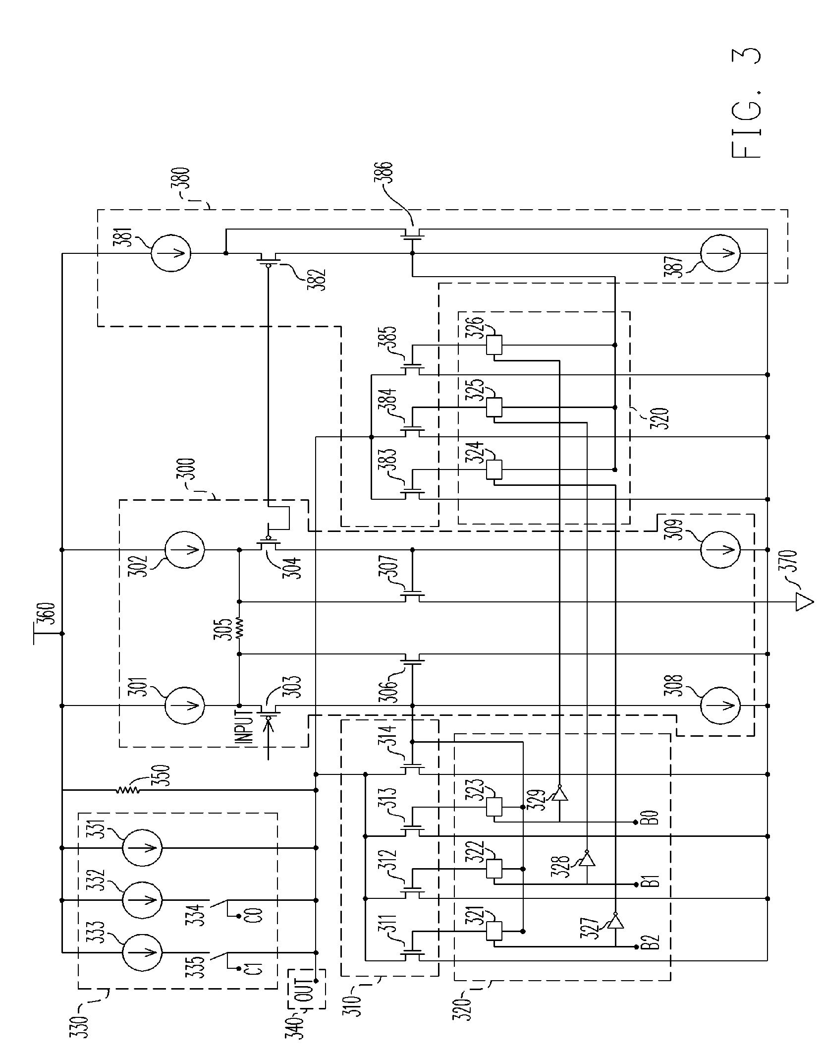
"The present invention provides a variable gain device (or amplifier) with higher linearity and wider gain range. Additionally, it can provide minimum unit gains to meet various systems. The invention also provides a variable gain amplifier with adjustable output DC level, which can overcome device error and device mismatch due to process parameter shift during the semiconductor manufacturing process. The output signal can easily meet the input signal range of the next stage unit through the adjustable output DC level control unit. The invention includes a transduction unit, a gain amplifying unit, a gain control unit, an output DC level control unit, and an output unit. The input voltage is converted by the transduction unit into an output current and the output current is outputted to the gain amplifying unit. The current gain of the gain amplifying unit is adjusted by the gain control unit according to a gain control signal of the VGA, and so the gain amplifying generates a gain adjustable current signal according to the gain control signal and the current signal. The DC level of the output signal of the VGA is adjusted by the output DC level control unit. The output unit receives the gain adjustable current signal and generates an output signal of the VGA."

Problems solved by technology

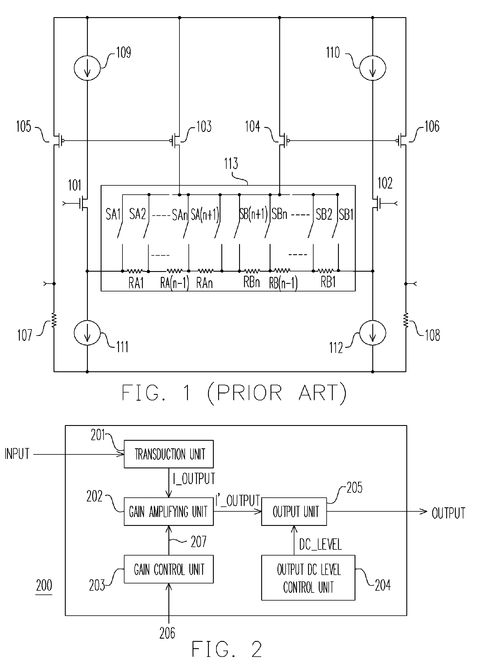
. . SB(n+1) when the switches are turned on changes along with the oscillation amplitude of the input signal; meanwhile, the internal resistance of each turned-on switch is different, and thus the output linearity is not adequate.
In addition, when the specification of the VGA requires wider gain range and smaller unit of gain, the number of attenuation resistors and switches required will be excessively large and complicated, which results in the increase in manufacturing cost.

Method used


Image

  • Variable gain device
  • Variable gain device
  • Variable gain device

Examples


Embodiment Construction

[0020]FIG. 2 is a circuit block diagram of a variable gain amplifier according to an embodiment of the present invention. Referring to FIG. 2, the variable gain amplifier (VGA) 200 includes the following: a transduction unit 201 for converting an input voltage INPUT into an output current I_OUTPUT; a gain control unit 203 for generating a gain control signal 207 according to a gain control signal 206 of the VGA 200; a gain amplifying unit 202 for receiving the output current signal I_OUTPUT output from the transduction unit 201, and the gain control signal 207, in which the circuit in the gain amplifying unit 202 is to determine a current gain with adjustable range according to the gain control signal 207, and an output signal I′_OUTPUT is generated by amplifying (or reducing) the current signal I_OUTPUT output from the transduction unit 201 based on the current gain; an output DC level control unit 204 for generating a DC level signal DC_LEVEL to adjust the DC level of the output s...


PUM


Abstract

A variable gain device having higher linearity and wider gain range is provided. The variable gain device includes a transduction unit for generating an output current, a control unit for adjusting the current gain of the gain amplifying unit according to a gain control signal, a gain amplifying unit receiving the current signal and generating a gain adjustable current according to the current gain of the control unit, an output DC level control unit controlling the DC level of the output signal of the variable gain device, and an output unit generating an output signal according to the signals output by the output DC level control unit and the gain amplifying unit.

Description

CROSS-REFERENCE TO RELATED APPLICATION[0001]This application claims the priority benefit of Taiwan application serial no. 94141248, filed on Nov. 24, 2005. All disclosure of the Taiwan application is incorporated herein by reference.BACKGROUND OF THE INVENTION[0002]1. Field of Invention[0003]The present invention relates to a device for signal processing. More particularly, the present invention relates to a variable gain signal processing device.[0004]2. Description of Related Art[0005]In an image signal processing system, the strength of the signal received by the system is always changed considerably during transmission. Thus, the circuits with auto gain control (AGC) are usually used to automatically adjust the strength of signal received by the system to meet the system's input signal specification. A variable gain device, or referred to as variable gain amplifier (VGA), is indispensable in an AGC system.[0006]To ensure the received signal meets various input signal specificati...

Claims


Application Information

Patent Timeline
Patent Type & Authority Patents(United States)
IPC IPC(8): H03F3/45
CPCH03F3/45197H03F3/45632H03G1/0088H03F2203/45101H03F2203/45352H03F2203/45646H03F2203/45681H03F2203/45726H03F2203/45641
Inventor YU, CHUNG-CHESHIU, SHIAN-SUNGLEE, LI-MIN
Owner BEYOND INNOVATION TECH
Learn More