
System and method for locomotive adhesion control

a technology for adhesion control and locomotives, applied in the direction of dynamo-electric converter control, motor/generator/converter stopper, multiple dynamo-motor starters, etc., can solve the problem of reducing or losing the adhesion of wheel-to-rail, excessive slippage of all vehicle wheels, and increased actual slippage or creep. the effect of the optimum creep

Active Publication Date: 2007-10-23
WESTINGHOUSE AIR BRAKE TECH CORP
View PDF12 Cites 24 Cited by
  • Summary
  • Abstract
  • Description
  • Claims
  • Application Information

AI Technical Summary

Benefits of technology

The patent describes a system and method for controlling the traction motor of a vehicle's propulsion system. The system includes a sensor to measure the speed of the wheel and another sensor to measure the amount of force applied by the wheel. Based on these measurements, the system's control circuitry adjusts the drive signals sent to the motor to optimize its performance. This results in a more efficient and effective vehicle that can better manage its traction on the road.

Problems solved by technology

Operation of any or all wheels away from the optimum creep, for instance, at too small a creep value or too large a creep value, may result in a reduction or loss of wheel-to-rail adhesion.
Likewise, if the wheel-to-rail adhesion tends to be reduced or lost, some or all the vehicle wheels may slip excessively, i.e., the actual slip speed or creep may be greater than the optimum creep.
Such a wheel slip condition, which is characterized in the motoring mode by one or more slipping axle-wheel sets and in the braking mode by one or more sliding or skidding axle-wheel sets, can cause accelerated wheel wear, rail damage, high mechanical stresses in the drive components of the propulsion system, and an undesirable decrease of tractive (or braking) effort.
There are many difficulties associated with determining an optimal creep set point for peak adhesion.
Direct measurement of the wheel tractive effort using strain gages for instance, is expensive, requiring significant changes to the wheels.
Moreover, the sensors used for direct measurement of wheel tractive effort are also prone to noise.
Such a method is also error prone owing to approximation of the dynamics of the drive train and related process noise.
This method especially loses it validity when the drive train resonates at its natural mode of vibration.
This will be the case when, for instance, the pitching and rolling modes of the trucks and platform of the locomotive resonate resulting in significant weight-shift effects and associated wheel normal force variations.
The resonance may typically manifest in significant oscillations in the motor torque adversely affecting the accuracy of torque maximization methods disclosed in prior art.
This method of determination of wheel speed is simplistic and is prone to errors owing to errors in motor speed measurement and also owing to approximation of the dynamics of the drive train while estimating wheel speed.
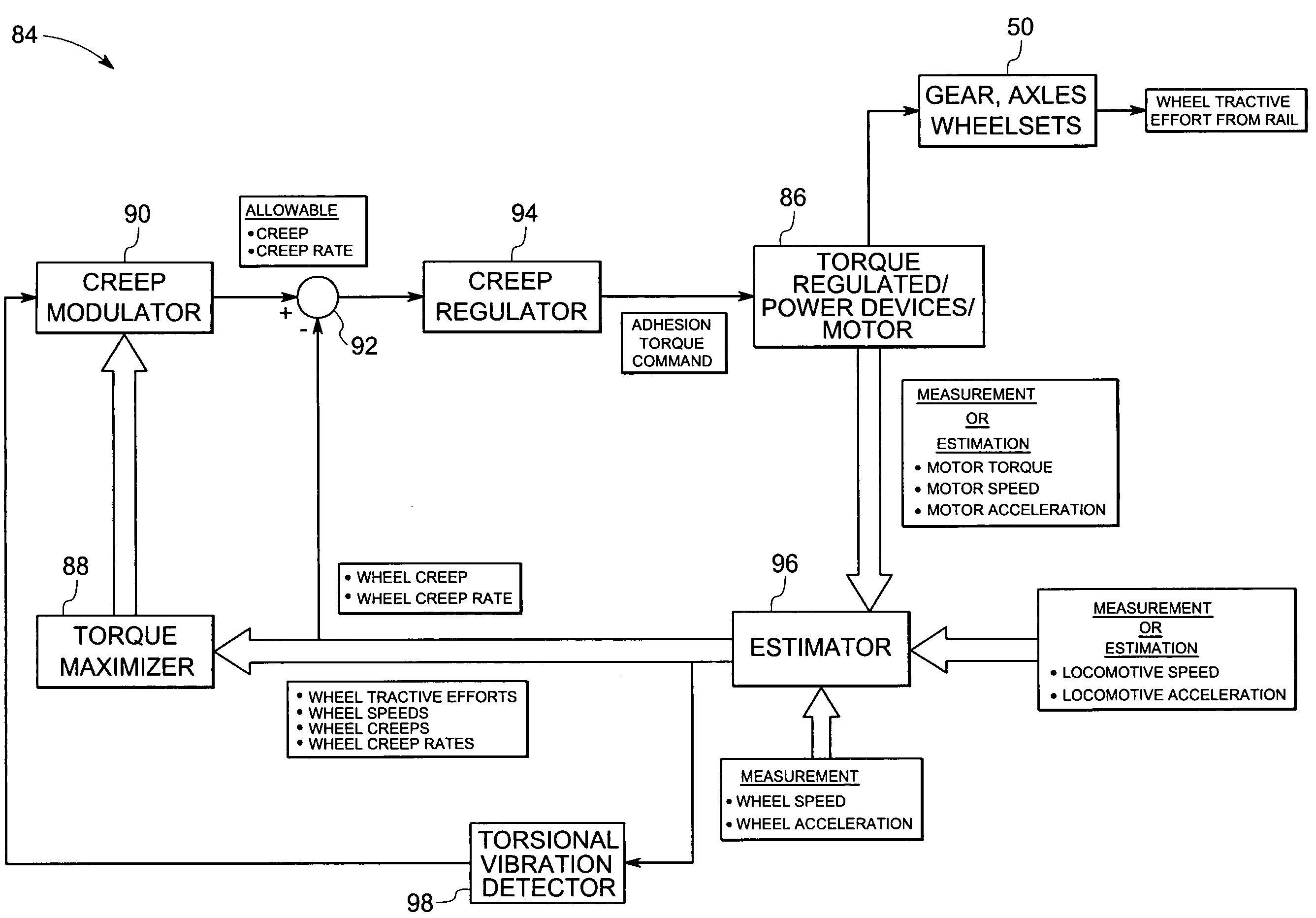
Another factor affecting traction performance is the level of torsional resonant vibration in the mechanical drive train, which comprises the axle and its associated two wheels, the motor to the axle gearbox, the traction motor and the traction motor drive.
In particular, during operation in certain regions of the adhesion characteristic curve, the mechanical drive train might experience a net negative damping, which produces severe vibration levels at natural frequencies or vibration modes of the system.
Dependent on the magnitude and duration of the vibration periods, the drive train may be damaged.
These issues in the measurement / estimation of wheel speed values and wheel tractive effort values result in an adhesion optimization system that usually operates sub-optimally.

Method used


Image

  • System and method for locomotive adhesion control
  • System and method for locomotive adhesion control
  • System and method for locomotive adhesion control

Examples


Embodiment Construction

[0020]Through the present discussion, it should be noted that the present invention may be utilized with various types of alternating current (AC) induction motor and DC motor powered vehicles such as off-highway vehicles (earth-moving machines), transit cars, and railroad locomotives. By way of example and not limitation, the invention is described herein as it may be applied to a locomotive.

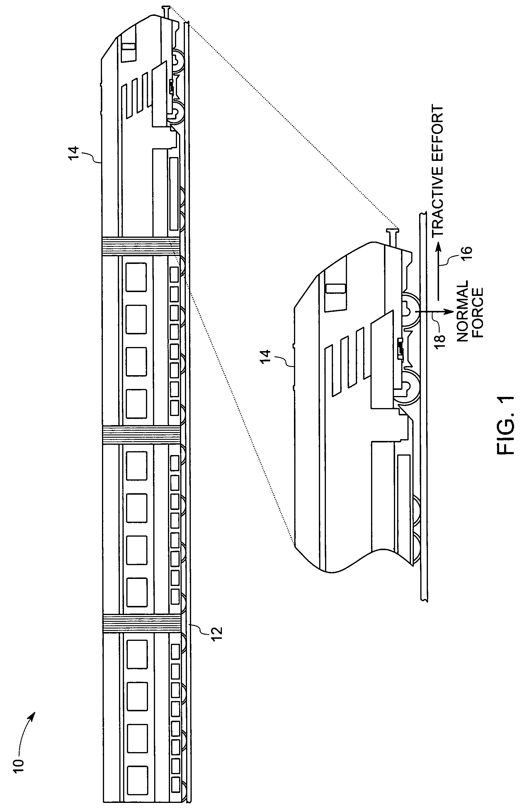
[0021]FIG. 1 is diagrammatical view of a train including a locomotive, and illustrating the tractive effort and adhesion of the locomotive controlled in accordance with an exemplary embodiment of this invention. The train 10 runs on rails 12. A locomotive 14 drives the train by means of electric traction motors at each axle-wheel set, as described in greater detail below. In the motoring mode of operation, these traction motors exert torque to the vehicle wheels, which exert tangential force or tractive effort on the surface such as the parallel steel rails of a railroad track on which the vehi...


PUM


Abstract

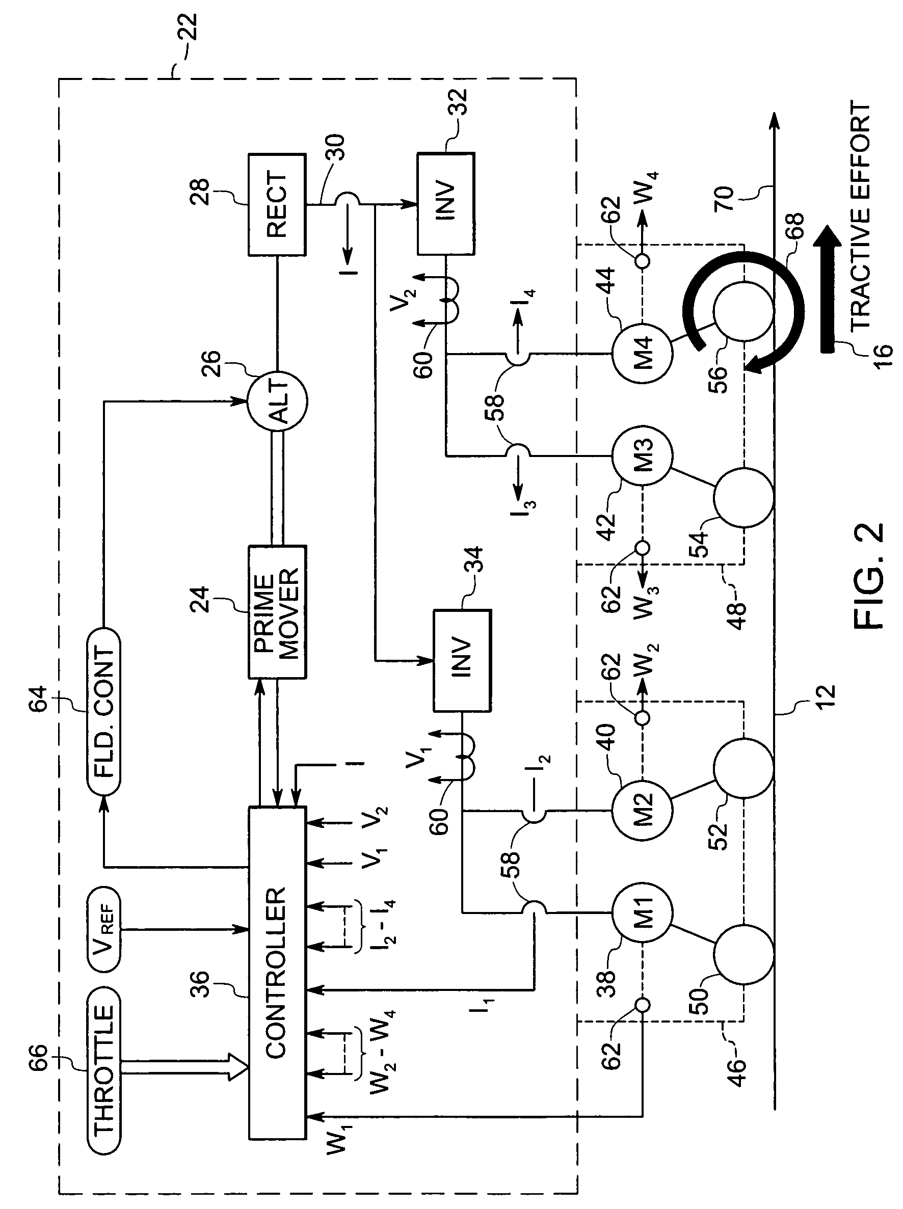
A traction control system for controlling an electric traction motor drivingly coupled to a wheel of a tractive vehicle. The traction control system includes means for determining speed of the wheel, means for determining tractive effort of the wheel and a control circuitry for controlling drive signals to the motor based upon the wheel speed and tractive effort.

Description

BACKGROUND[0001]The present invention relates generally to the field of locomotives and their control. More particularly, the invention relates to techniques for maximizing the tractive effort or braking effort of a locomotive and minimizing the resonant torsional vibration per axle to improve overall performance.[0002]Locomotives and transit vehicles as well as other large traction vehicles are commonly powered by electric traction motors coupled in driving relationship to one or more axles of the vehicle. Such locomotives and transit vehicles typically have at least four axle-wheel sets per vehicle with each axle-wheel set being contacted via suitable gearing to the shaft of a separate electric motor commonly referred to as a traction motor. In a motoring mode of operation, the traction motors are supplied with electric current from a controllable source of electric power such as an engine-driven traction alternator. The traction motors apply torque to the vehicle wheels, which in...

Claims


Application Information

Patent Timeline
Patent Type & Authority Patents(United States)
IPC IPC(8): B61C15/08
CPCB60L3/10B60L3/102B60T8/1705B60T8/172B61C15/14B60L2200/26Y02T10/646Y02T10/648B60T2210/12Y02T10/64
Inventor MCGARRY, JEREMY THOMASRAMACHANDRA-PANICKER, SOMAKUMARKUMAR, AJITH KUTTANNAIRRYALI, VENKATARAOWORDEN, BRET DWAYNEDAIGLE, JEFFREY LOUISHOUPT, PAUL KENNETH
Owner WESTINGHOUSE AIR BRAKE TECH CORP
Learn More