
Self-piercing rivet setting die and apparatus

a rivet and setting die technology, applied in the direction of screwdrivers, threaded fasteners, manufacturing tools, etc., can solve the problems of inability to reliably connect the workpieces, inability to provide a sufficient connection strength, and inability to welding aluminum panels for automobiles and the like, etc., to achieve the effect of reliably connecting the workpieces

Inactive Publication Date: 2007-10-23
KONE CORP +1
View PDF16 Cites 36 Cited by
  • Summary
  • Abstract
  • Description
  • Claims
  • Application Information

AI Technical Summary

Benefits of technology

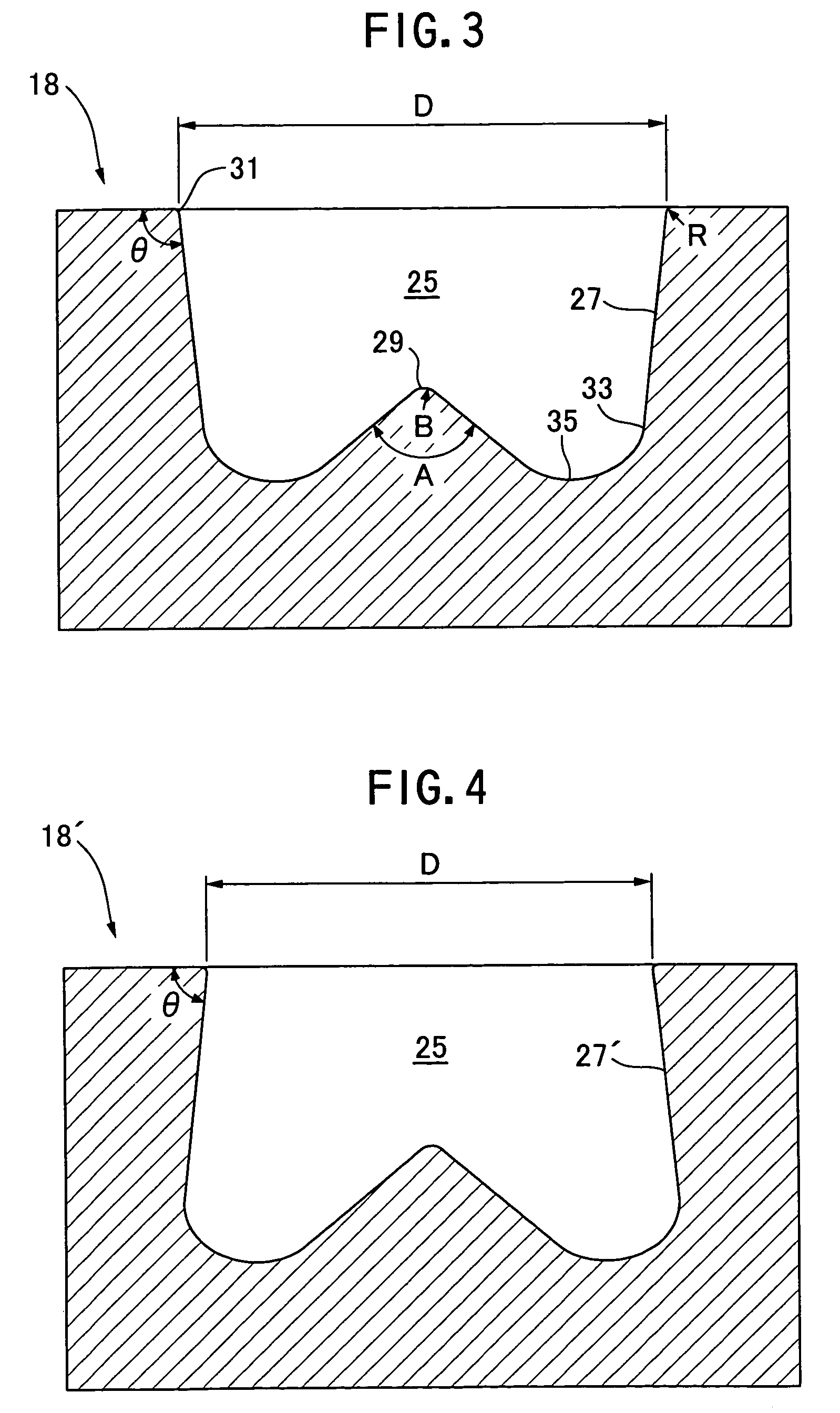
The present invention is related to a die for use in a self-piercing rivet setting apparatus. The die has a cavity for receiving the protruded workpiece zone consisting of the portions of the workpieces to be protrudingly deformed towards the die by the pressure of the self-piercing rivet. The cavity has a central raised portion and an upper end with a small radius or bevel. The material of the workpieces flows along the central raised portion and the curved inner surface of the cavity from the bottom towards the outer wall of the cavity, and then flows upward along the outer wall after changing its direction. This material flow results in an undercut in the receiving-side workpiece, which ensures reliable connection. The technical effect of the invention is to provide a reliable and efficient method for connecting multiple workpieces by self-piercing rivet.

Problems solved by technology

Aluminum panels for an automobile and the like are not suitable for welding, and therefore are typically connected using self-piercing rivets.
In this conventional self-piercing-rivet driving operation, however, if the punch-side workpiece is thick and the receiving-side workpiece adjacent to the die is thin, then the leg of the rivet does not penetrate into the receiving-side workpiece adjacent to the die and consequently it is unable to provide a sufficient strength for the connection.
Also, in the conventional self-piercing-rivet driving operation, if more than two workpieces are to be connected, then the leg of the rivet does not penetrate sufficiently through the receiving-side workpiece adjacent to the die, and thereby it is difficult to reliably connect the workpieces together.

Method used


Image

  • Self-piercing rivet setting die and apparatus
  • Self-piercing rivet setting die and apparatus
  • Self-piercing rivet setting die and apparatus

Examples


example 1

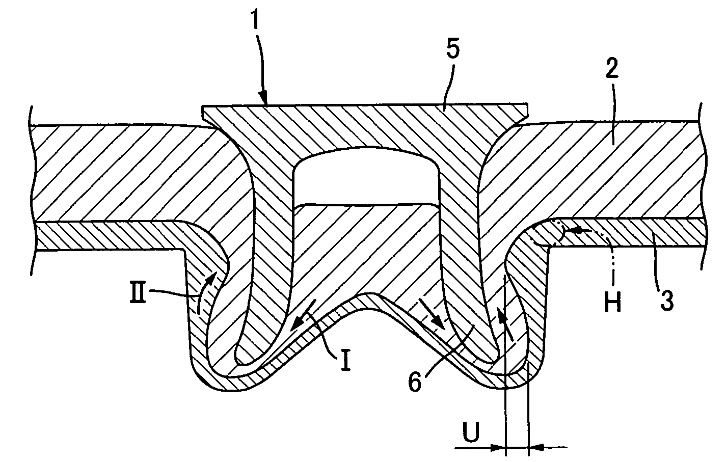
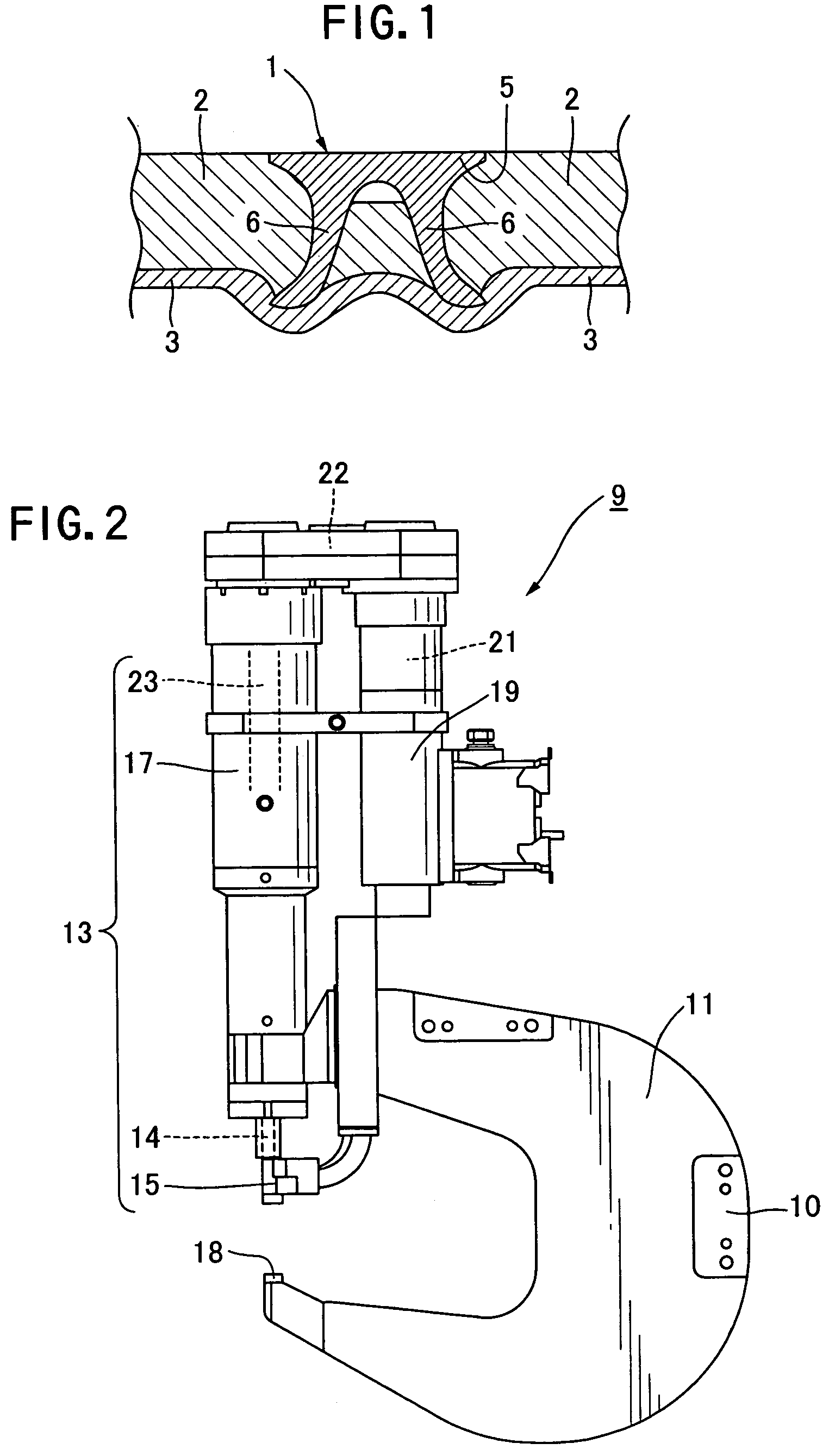
[0064]FIG. 9 is a sectional view illustrating the state where the workpieces 2 and 3 are connected by the self-piercing rivet 1 using the die 18 according to the present invention. In Example 1, due to the shape of the cavity 25 of the die 18, the material of the workpieces flows well within the cavity 25. The receiving-side workpiece 3 has the squeezed configuration in the upper part of the cavity thereby creating the undercut, and thus the workpieces are reliably connected. As a result, the thick workpiece 2 and the thin receiving-side workpiece 3 are not easily separated.

example 2

[0067]FIG. 11 is a sectional view illustrating the state where three workpieces 2, 2′, and 3 are connected by the self-piercing rivet 1 using the die according to the present invention. In Example 2, the receiving-side workpiece 3 is squeezed at the upper part of the cavity and thus the undercut is formed. Therefore, after the workpieces are connected, the receiving-side workpiece will not separate from the interface therebetween.

[0068]As described above, when the workpieces are connected by the self-piercing rivet using the die according to the present invention, a smooth flow of the material of the workpieces can be formed upon connecting the workpieces, and as a result the receiving-side workpiece has the squeezed configuration in the upper part of the cavity, thereby creating the undercut. Therefore, the workpieces can be connected more reliably than the case where the self-piercing rivet connects the workpieces using the conventional die.

[0069]In particular, when the receiving-...


PUM

PropertyMeasurementUnit
vertical angleaaaaaaaaaa
angleaaaaaaaaaa
angleaaaaaaaaaa

Abstract

A die (18) for use in a self-piercing rivet setting apparatus comprises a cavity (25) for receiving therein a protruded workpiece zone consisting of respective portions of the workpieces (2, 3) to be protrudingly deformed toward the die through the pressure of the self-piercing rivet (1). The cavity has a bottom surface provided with a central raised portion (29) protruding from the center of the bottom surface toward a punch. The central raised portion of the cavity has a vertical angle in the range of 90 to 160 degrees. Preferably, the central raised portion has a top formed in a spherical shape. The cavity has an approximately cylindrical outer wall (27) in the periphery thereof. The cavity has a curved inner surface extending from the top of the central raised portion to the lower end (33) of the outer wall through the bottom (35) of the cavity.

Description

CROSS-REFERENCES TO RELATED APPLICATIONS[0001]This application is a continuation of international patent application PCT / US2003 / 03725 which was filed on Feb. 6, 2003 designating the U.S., and which claims priority from Japanese patent application 2002-032538, filed on Feb. 8, 2002.FIELD OF THE INVENTION[0002]The present invention relates to a self-piercing rivet setting apparatus for setting in a plurality of workpieces a self-piercing rivet having a large-diameter head and a hollow leg extending downward from the head, and a die for use in the apparatus. More specifically, the present invention relates to a self-piercing rivet setting apparatus for connecting a plurality of workpieces with one another, such as two or more sheet members (or a sheet member and a component), by using a self-piercing rivet in a sheet-like metal assembling operation such as automobile assembling (particularly, an aluminum body assembling operation), and a die for use in the apparatus.BACKGROUND OF THE I...

Claims


Application Information

Patent Timeline
Patent Type & Authority Patents(United States)
IPC IPC(8): B23P21/00B21D15/10B21D39/00F16B19/08F16B37/04B21J15/02B21J15/36
CPCB21J15/025B21J15/36Y10T29/49837Y10T29/49943Y10T29/5343Y10T29/5377Y10T29/49956
Inventor KATO, TORUUMEMURA, HIRONORINAITOH, NOBUHARU
Owner KONE CORP
Learn More