Image forming apparatus and polishing method for image carrier

a technology of image carrier and forming apparatus, which is applied in the direction of electrographic process apparatus, instruments, optics, etc., can solve the problems of poor charge area, wasteful consumption of toner t, and waste of toner t, so as to reduce the abrasion or marring of the image carrier surface

Inactive Publication Date: 2007-10-16
KONICA MINOLTA BUSINESS TECH INC
View PDF10 Cites 5 Cited by
  • Summary
  • Abstract
  • Description
  • Claims
  • Application Information

AI Technical Summary

Benefits of technology

[0014]In an image forming apparatus including: an image carrier driven into rotation; a charger for electrically charging a surface of the image carrier; a latent image forming unit for forming an electrostatic latent image on the charged image carrier surface; a developing unit for forming a toner image by supplying a toner to an area of the electrostatic latent image formed on the image carrier surface; and a transferring unit for transferring the toner image formed on the image carrier surface to a transfer medium, an object of the invention is to reduce abrasion or marring of the image carrier surface so as to prevent the toner and the like remaining on the image carrier surface after image transfer from filming as fused to the image carrier surface.
[0016]In the image forming apparatus according to the invention, the non-rotary type polishing member employing the foamed elastic material is contacted against the surface of the image carrier at place downstream from the transferring unit in the moving direction of the image carrier and between the transferring unit and the charger and is reciprocally moved in the direction intersecting with the moving direction of the image carrier. Therefore, the surface of the image carrier is properly polished by the polishing member so that the abrasion or marring of the image carrier surface is reduced while the toner and the like remaining on the image carrier surface after image transfer are positively prevented from filming as fused to the image carrier surface. Thus is ensured that images of good quality are formed in a stable manner.

Problems solved by technology

In the above case where the toner t remaining on the image carrier surface 1 is removed by the cleaner 7, the toner t is wastefully consumed because it is a general practice to dispose of the collected toner t. In addition, the disposal of the waste toner t poses a problem.
However, such a cleaner-less image forming apparatus has the following problem.
If a large quantity of toner remains on the image carrier surface after image transfer, the residual toner on the image carrier surface may produce a poorly charged area or may disable the latent image forming unit to form a proper electrostatic latent image.
In consequence, the formed images may suffer density irregularities or an afterimage may appear in the subsequently formed image.
However, in the above constitution wherein the toner remaining on the image carrier surface after image transfer is dispersed by the dispersing member such as the foam roller or rotary brush, so as to be collected by the developing unit, the developing unit is incapable of adequately removing, from the image carrier surface, the residual toner after image transfer, an external additive of the toner or corona products produced during the charging process.
Hence, these substances are fused to the image carrier surface to form film, which degrades the quality of the formed images.
Hence, the apparatus has the same problems as those of the conventional apparatuses.
Furthermore, the abrasive particles heavily abrade the surface of the image carrier so that the image carrier is increased in the surface roughness, thus adversely affecting the image to be formed.

Method used


Image

  • Image forming apparatus and polishing method for image carrier
  • Image forming apparatus and polishing method for image carrier
  • Image forming apparatus and polishing method for image carrier

Examples


Embodiment Construction

[0027]An image forming apparatus according to an embodiment of the invention will be specifically described with reference to the accompanying drawings. It is to be noted that the image forming apparatus according to the invention is not limited to those illustrated by the following embodiments and may be modified as needed so long as such a modification does not depart from the scope of the invention.

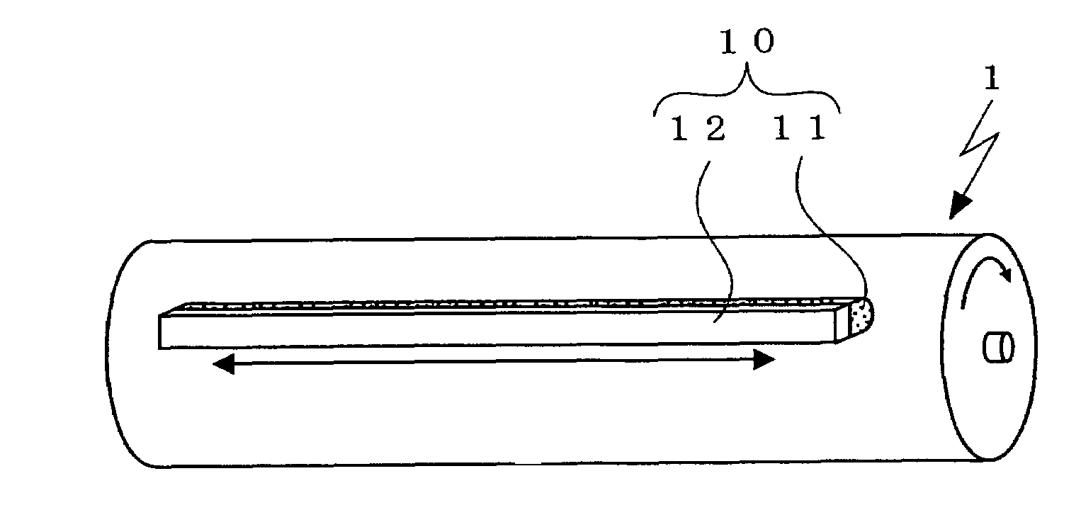
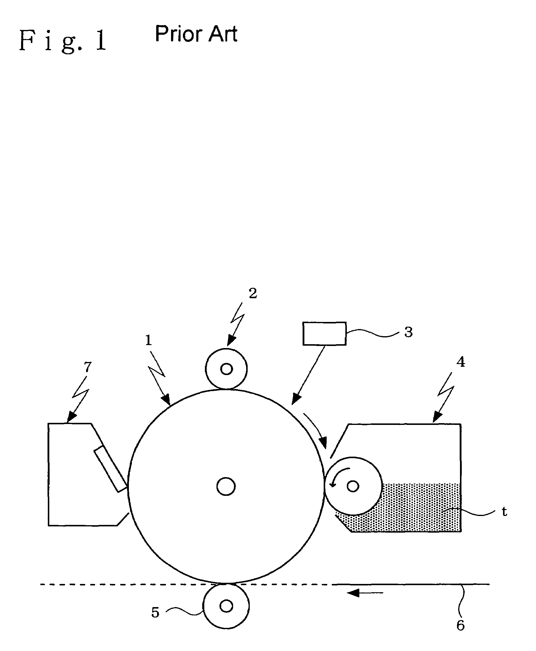
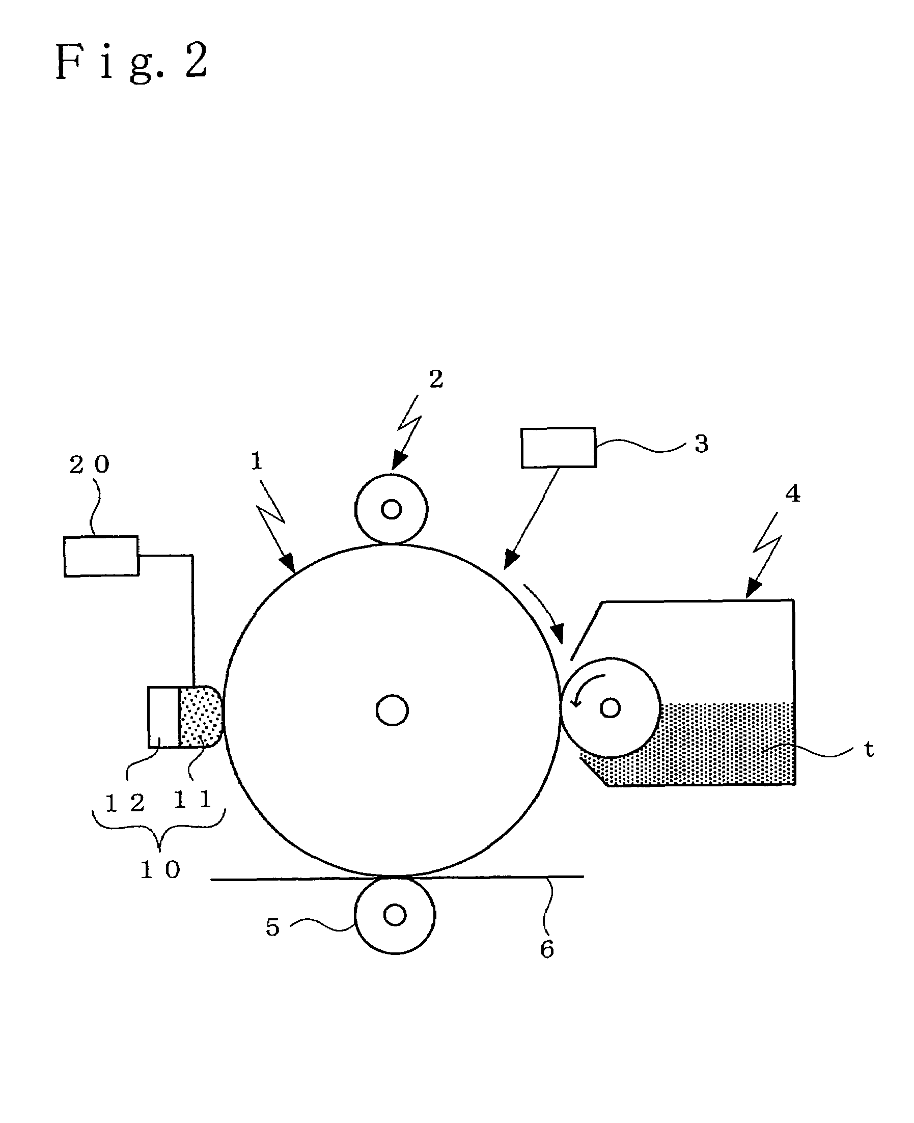
[0028]The image forming apparatus of the embodiment is adapted to form an electrostatic latent image on a surface of an image carrier 1 as follows. As shown in FIG. 2, the surface of the rotating image carrier 1 is electrically charged by a charger 2. Subsequently, a latent image forming unit 3 employing a laser or the like irradiates light on the surface of the image carrier 1 according to image information, thereby forming the electrostatic latent image on the image carrier surface 1.

[0029]Subsequently, a developing unit 4 supplies a toner t to an area of the electrostatic latent ima...


PUM


Abstract

An image forming apparatus comprises: an image carrier driven into rotation; a charger for electrically charging a surface of the image carrier; a latent image forming unit for forming an electrostatic latent image on the charged image carrier surface; a developing unit for forming a toner image by supplying a toner to an area of the electrostatic latent image formed on the image carrier surface; a transferring unit for transferring the toner image formed on the image carrier surface to a transfer medium; and a non-rotary type polishing member employing a foamed elastic material, the polishing member contacted against the surface of the image carrier at place downstream from the transferring unit in a moving direction of the image carrier and between the transferring unit and the charger, and reciprocally moved in a direction intersecting with the moving direction of the image carrier.

Description

RELATED APPLICATION[0001]This application is based on an application No. 130920 / 2006 filed in Japan, the contents of which are hereby incorporated by reference.BACKGROUND OF THE INVENTION[0002]1. Field of the Invention[0003]The present invention relates to an image forming apparatus utilizing an electrophotographic system, such as copiers and printers, as well as to a polishing method for image carrier. Particularly, in an image forming apparatus including: an image carrier driven into rotation; a charger for electrically charging a surface of the image carrier; a latent image forming unit for forming an electrostatic latent image on the charged image carrier surface; a developing unit for forming a toner image by supplying a toner to an area of the electrostatic latent image formed on the image carrier surface; and a transferring unit for transferring the toner image, formed on the image carrier surface, to a transfer medium, the invention is characterized by reducing the abrasion ...

Claims


Application Information

Patent Timeline
Patent Type & Authority Patents(United States)
IPC IPC(8): G03G15/30
CPCG03G21/007G03G21/0047
Inventor HAGIMOTO, NORITOSHI
Owner KONICA MINOLTA BUSINESS TECH INC
Why Eureka
Try Eureka