
H-bridge utilizing intermediate switching phase(s)

Active Publication Date: 2007-10-09
AMI SEMICON BELGIUM
View PDF4 Cites 4 Cited by
  • Summary
  • Abstract
  • Description
  • Claims
  • Application Information

AI Technical Summary

Benefits of technology

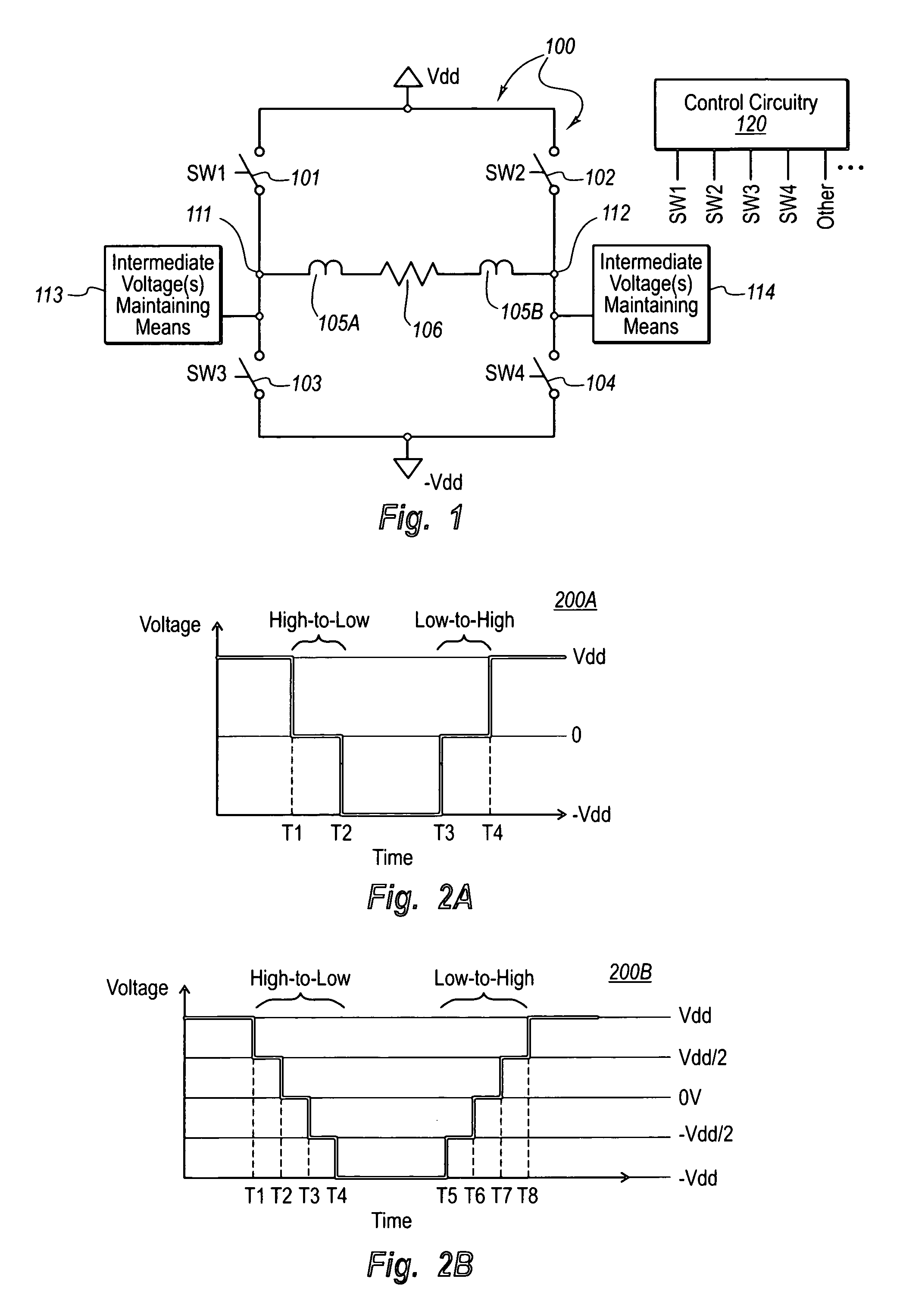
[0011]The principles of the present invention relate to an H-bridge circuit that may serve as a Class D amplifier, and is capable of performing switching between a high voltage and a low voltage using one or more intermediate voltage phases each held for a period of time in the midst of the switching operation. This reduces power dissipation associated with the switching operation, while only using one set of high / low voltage supplies. Furthermore, the use of intermediate voltages in the switching operation mitigates the often undesirable impact of harmonics typically generated by a sudden switching operation.
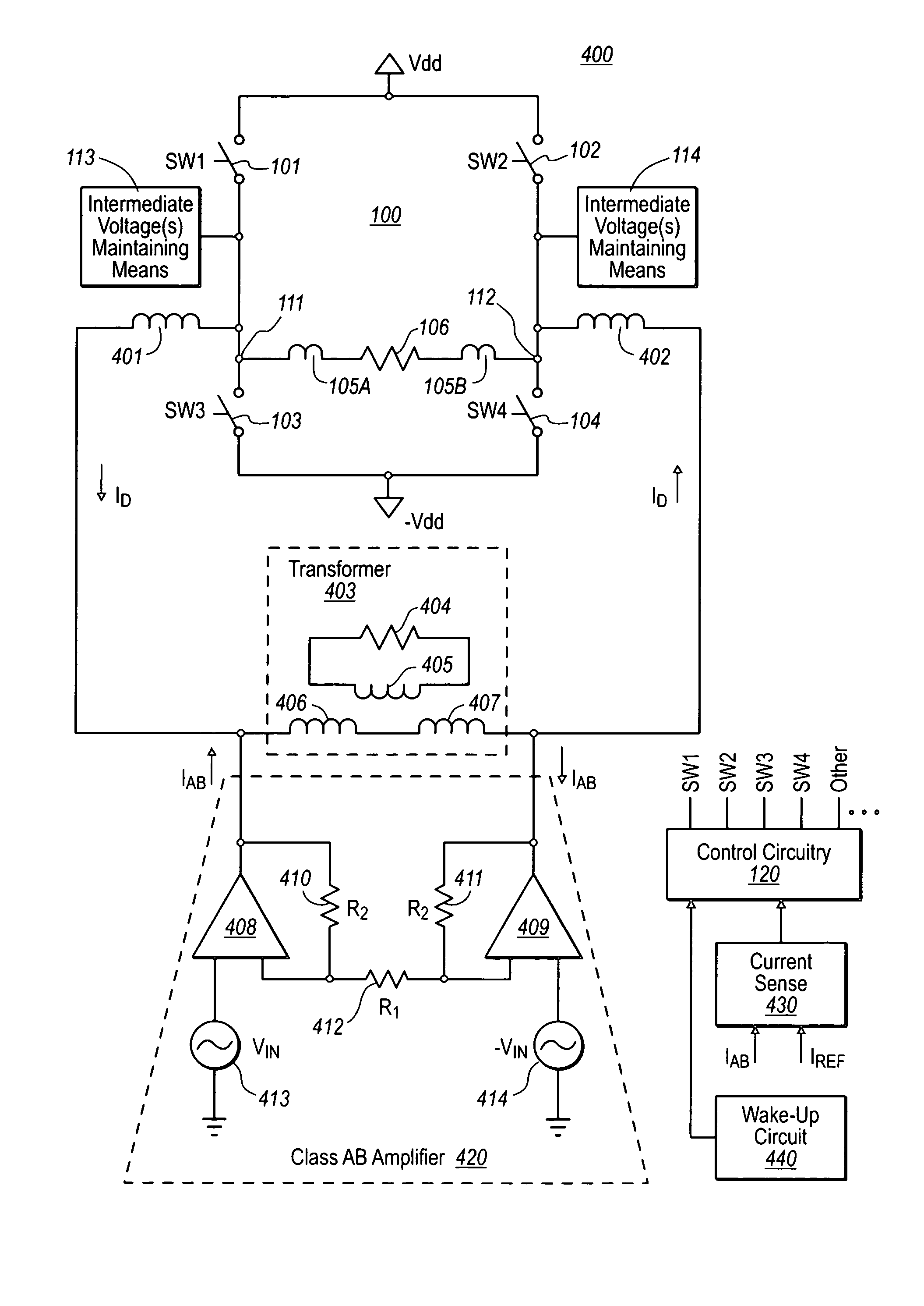
[0013]Although the class AB amplifier is not highly efficient, its power requirements are kept low by triggering the H-bridge to change states and provide more current when the class AB amplifier current reaches a reference value. Thus, the class AB amplifier delivers little current, and thus the low efficiency of the class AB amplifier has less negative impact on the overall high efficiency of the combination class D and class AB amplifiers. Therefore, the combination of the H-bridge and class AB amplifier allows for a highly efficient and controlled mechanism for driving a load. Furthermore, the use of intermediate voltages in the H bridge allows for increased slew rates for any given operation frequency, and allows for the driving of a given signal on the load using a lower operational frequency.

Problems solved by technology

Although the class AB amplifier is not highly efficient, its power requirements are kept low by triggering the H-bridge to change states and provide more current when the class AB amplifier current reaches a reference value.
Thus, the class AB amplifier delivers little current, and thus the low efficiency of the class AB amplifier has less negative impact on the overall high efficiency of the combination class D and class AB amplifiers.

Method used


Image

  • H-bridge utilizing intermediate switching phase(s)
  • H-bridge utilizing intermediate switching phase(s)
  • H-bridge utilizing intermediate switching phase(s)

Examples


Embodiment Construction

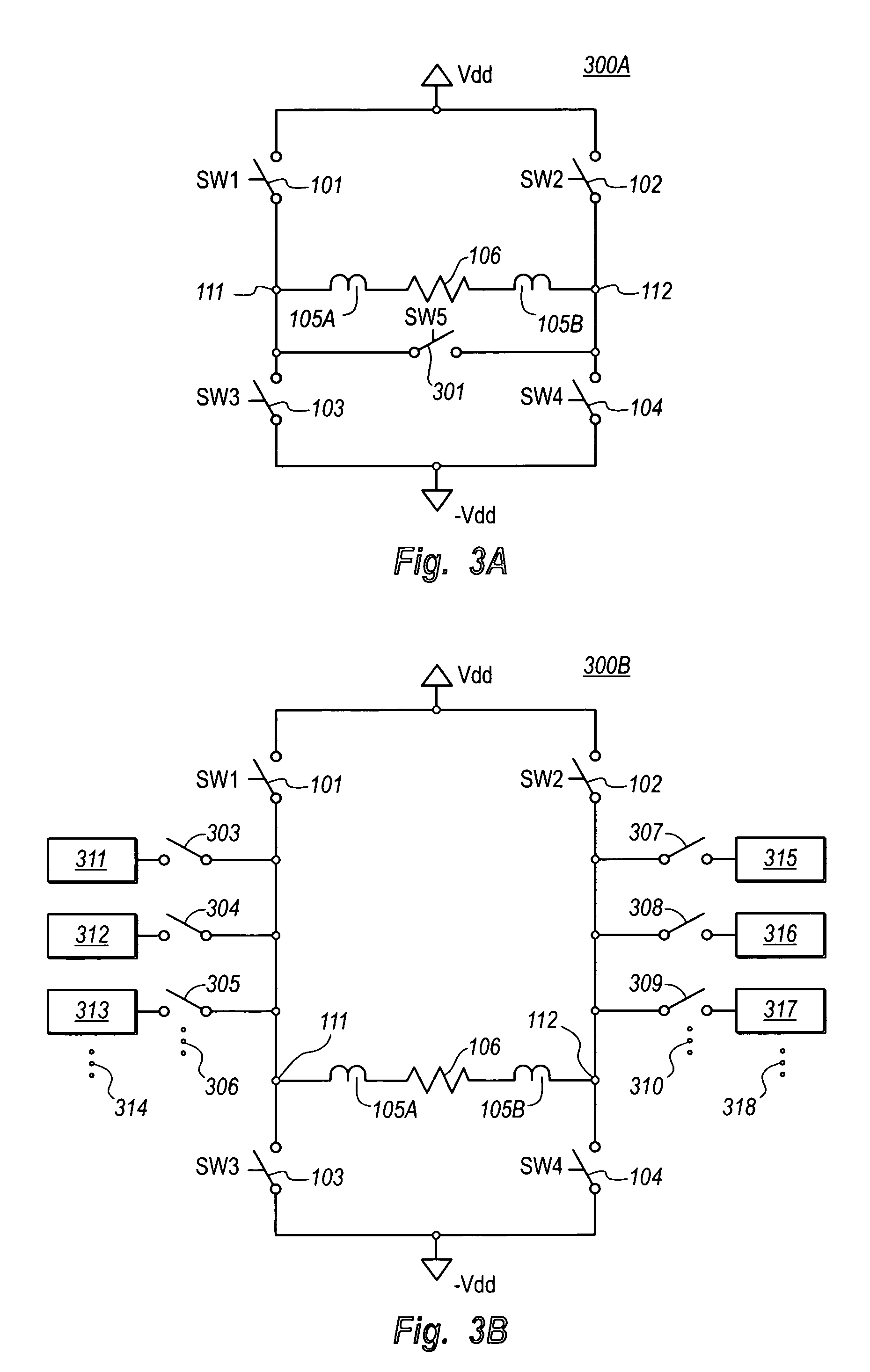
[0032]The principles of the present invention relate to an H-bridge circuit that may serve as a Class D amplifier, and that is capable of performing switching using one or more intermediate voltage phases or states, each intermediate voltage phase being held for a period of time in the midst of the switching operation. This reduces power dissipation associated with the switching operation, while only using one set of high / low voltage supplies. In an alternative embodiment, the H-bridge may be used to provide current via an inductor to a load. A class AB amplifier may be placed in parallel with the H-bridge to provide supplemental correcting current to the load to allow the combination to act as an efficient and accurate signal driver. Furthermore, the use of intermediate voltages in the H-bridge allows for increased slew rates for any given operation frequency, and allows for the driving of a given signal on the load using a lower operational frequency.

[0033]FIG. 1 illustrates an H-...


PUM


Abstract

An H-bridge circuit capable of performing switching using one or more intermediate voltage phases each held for a period of time in the midst of the switching operation. This reduces power dissipation associated with the switching operation, while only using one set of high / low voltage supplies. The H-bridge may be used to provide current via an inductor to a load. A class AB amplifier may be placed in parallel with the H-bridge to provide supplemental correcting current to the load to allow the combination to act as an efficient and accurate signal driver. Furthermore, the use of intermediate voltages in the H bridge allows for increased slew rates for any given operation frequency, and allows for the driving of a given signal on the load using a lower operational frequency.

Description

CROSS-REFERENCE TO RELATED APPLICATIONS[0001]This patent application claims the benefit of U.S. provisional patent application Ser. No. 60 / 719,768, filed Sep. 23, 2005, which provisional patent application is incorporated herein by reference in its entirety.BACKGROUND OF THE INVENTION[0002]1. The Field of the Invention[0003]The principles of the present invention relate to a class D amplifier implemented as an H-bridge that implements switching using one or more intermediate switching phases.[0004]2. The Relevant Technology[0005]Electronic circuitry provides complex functionality that is proving ever more, useful. Electronic circuitry pervades our modern lives in areas such as communication, entertainment, travel, productivity, and the like. One common type of circuit is the class D amplifier, which performs switching operations to generate a pulse signal. If an input signal increases to have a higher voltage than a reference voltage, the output pulse signal transitions from one bin...

Claims


Application Information

Patent Timeline
IPC IPC(8): H03F3/217
CPCH03F3/2173H03F2200/432H03F2200/351
Inventor SEVENHANS, JOANNES MATHILDE JOSEPHUSMACQ, DAMIEN LUC FRANCOISCASIER, HERMAN JORISJANSSENS, JOHAN CAMIEL JULIA
Owner AMI SEMICON BELGIUM
Learn More