
Swivel device utilizing bearing clearance to allow carbon dioxide laden exhaust

a technology of bearing clearance and swivel conduit, which is applied in the direction of respiratory apparatus, medical devices, other medical devices, etc., can solve the problems of repeated interruption of sleep in patients, drawbacks of ports in the body of the mask, etc., and achieves less perceptible sensation, easy disassembly and cleaning, and reduced sound intensity

Inactive Publication Date: 2007-10-09
RIC INVESTMENTS LLC
View PDF20 Cites 9 Cited by
  • Summary
  • Abstract
  • Description
  • Claims
  • Application Information

AI Technical Summary

Benefits of technology

[0007]The improved swivel conduit rotatably connects a patient mask to the delivery conduit of the present invention of a positive pressure air supply. The improved design provides an exhaust vent for purging the system of CO2 laden air that utilizes the rotating bearing of its two-piece design. A baffle chamber in the design reduces the intensity of the sound generated. As CO2 laden exhaust exits the swivel conduit, it is directed away from the patient mask and down the outside of the delivery conduit via a slit pattern on the swivel conduit. The unique two-peice bearing design may be easily disassembled for cleaning.

Problems solved by technology

As a consequence, there is repeated interruption of sleep in the patient.
However, several drawbacks are associated with ports in the body of the mask.
For example, air exiting the mask ports may create noise or blow on the patient, causing discomfort.

Method used


Image

  • Swivel device utilizing bearing clearance to allow carbon dioxide laden exhaust
  • Swivel device utilizing bearing clearance to allow carbon dioxide laden exhaust
  • Swivel device utilizing bearing clearance to allow carbon dioxide laden exhaust

Examples


first embodiment

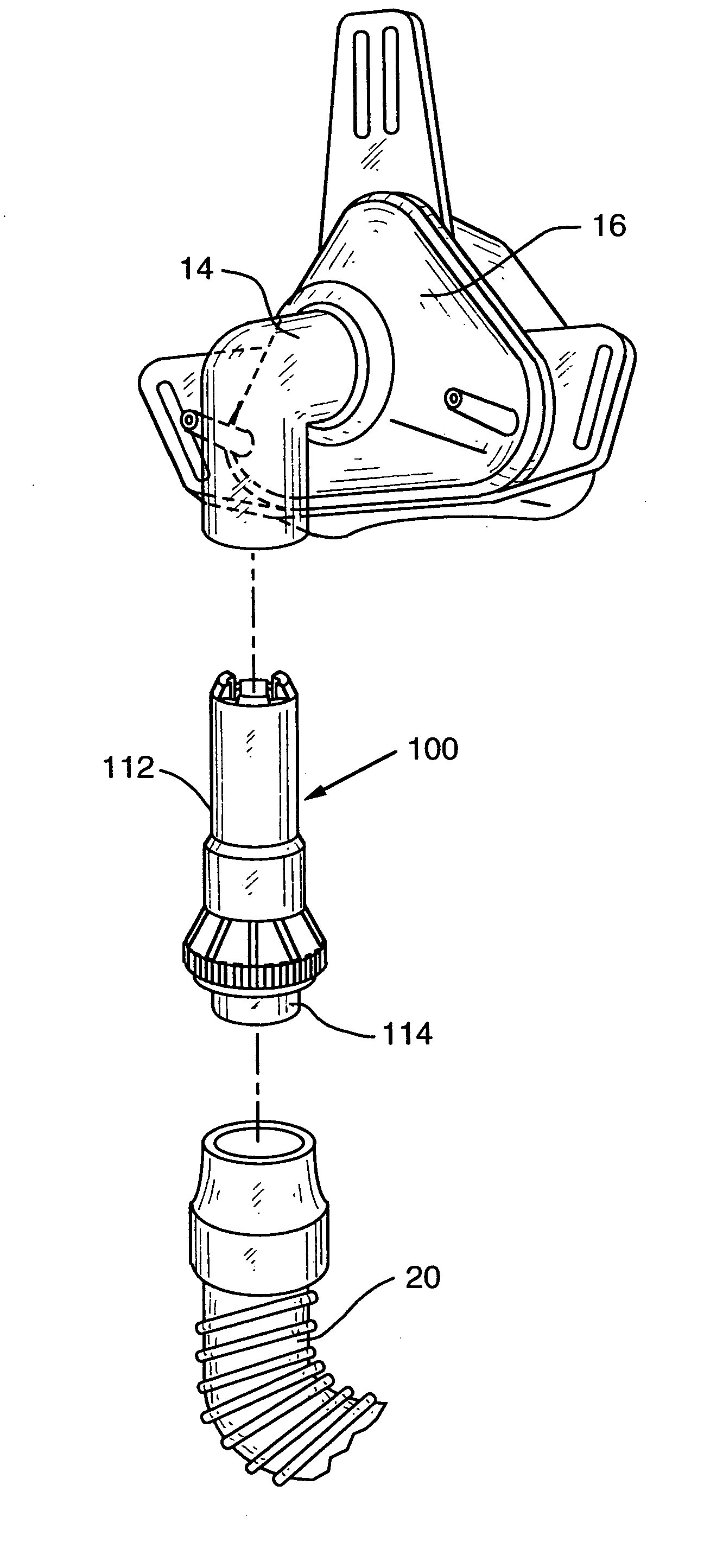
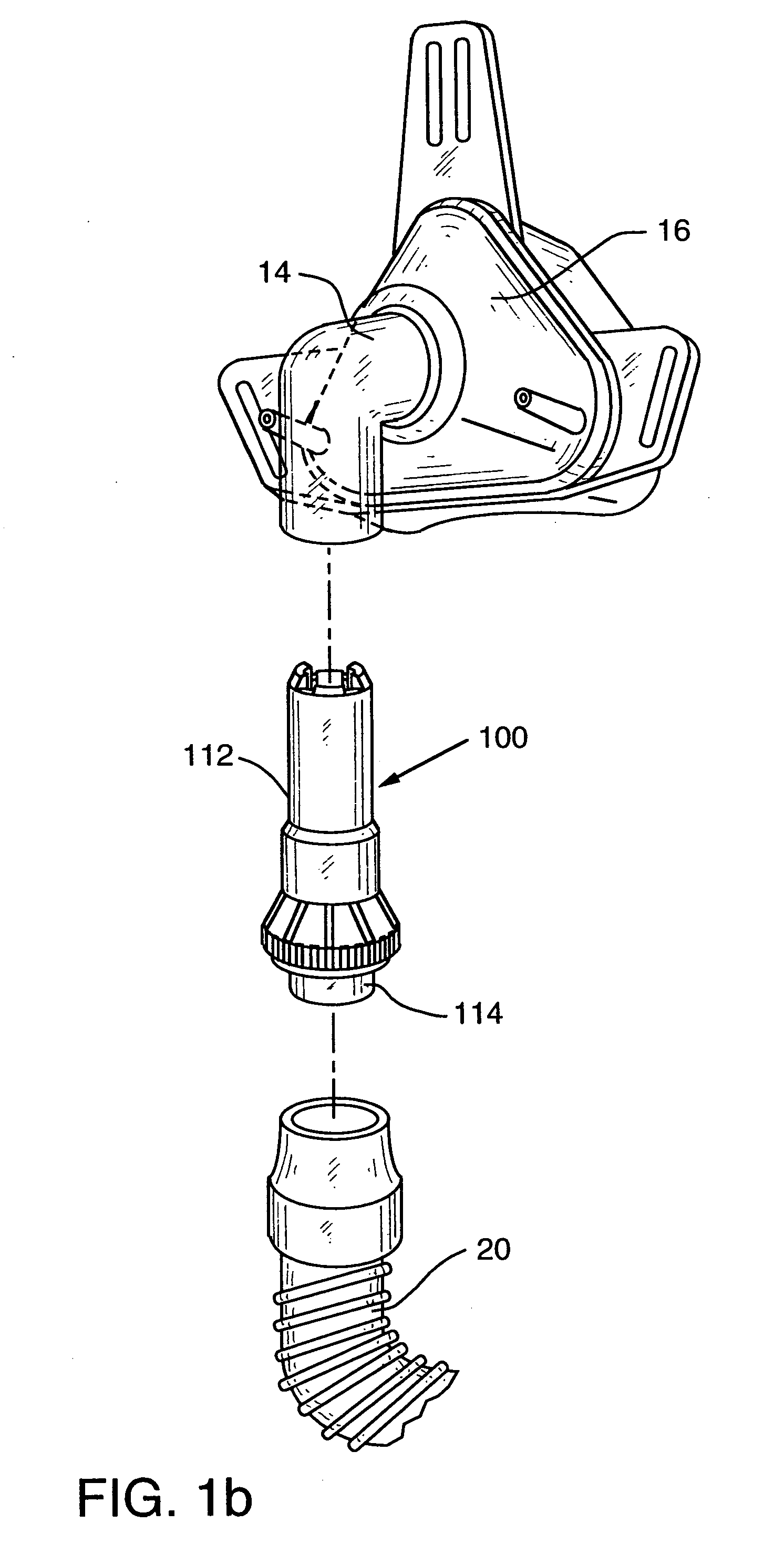
[0020]FIGS. 1b, 2, 3 and 4 illustrate an improved swivel exhaust device 100. The improved two-piece design has a mask connection piece 112, which is received within one end of an L-shaped mask conduit 14, and a delivery conduit piece 114, which is received within one end of the delivery conduit 20. The mask connection piece 112 and the delivery conduit piece 114 are rotatably coupled to each other. Discharge of CO2 laden expiratory exhaust is permitted through the clearance 116 between the mask connection piece 112 and the delivery conduit piece 114.

[0021]The mask connection piece 112 generally comprises a tubular mask connection end 118 which is received in the L-shaped mask conduit 14, an intermediate stepped portion 120 having a larger diameter than the mask connection end 118, and a radial exhaust end 122 opposite the mask connection end 118. The stepped portion 120 is joined to the mask connection 118 end by a sloped portion 124 whose diameter increases from the mask connection...

second embodiment

[0026]A swivel conduit 200 in accordance with the present invention is shown in FIG. 5. In this embodiments, the stepped portion of the delivery conduit piece 214 includes a raised baffle 250 to reduce noise. In this embodiment, as well as in the embodiments illustrated in FIGS. 6 and 7, the two shorter retaining arms 242 preferably do not have radial segments. Alternately, in an unillustrated embodiment, all retaining arms are the same longer length with the two arms which are pressed inwardly for disassembly having locating notches.

third embodiment

[0027]A swivel conduit 300 in accordance with the present invention is shown in FIG. 6. In this embodiment1 spaced radial holes 360 are provided (preferably four) in the stepped portion 350 of the delivery conduit piece 314 to provide an additional path for CO2 laden exhaust between the interior of the delivery conduit piece 314 and the baffle chamber 358. Hole bosses 362 protrude inwardly to divert fluids or secretions around the holes. In this embodiment, CO2 laden exhaust flow is determined by both the holes 360 and the clearance 316 between the mask connection piece 312 and the delivery conduit piece 314.

[0028]In a swivel conduit 400 of a fourth preferred embodiment illustrated in FIG. 7 of the present invention, the delivery conduit piece 414 includes a baffle portion 452 as described in accordance with FIG. 5. Also, each of the longitudinal slots 440 of the swivel connection end 438 ends in a hole 464. These holes 464 are preferably angled for manufacturing purposes but could ...


PUM


Abstract

A swivel exhaust conduit for rotatably connecting a patient mask to the delivery conduit of a positive pressure air supply. The swivel exhaust conduit design provides an exhaust port that utilizes the rotating bearing of the swivel conduit's rotating two-piece design for permitting and directing exhaust of CO2 laden air. A baffle chamber formed in the clearance of the two pieces provides an area where noise is reduced. As CO2 laden exhaust exits the swivel exhaust conduit, it is directed away from the patient mask and down the outside of the delivery conduit via a slit pattern on the swivel conduit.

Description

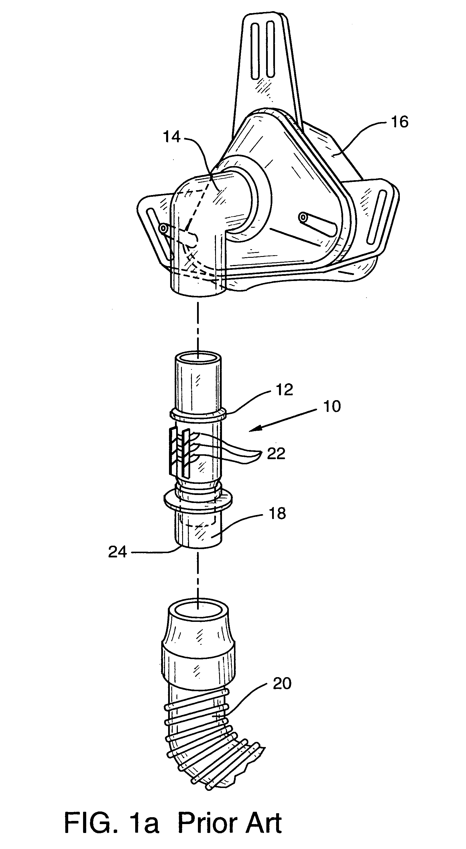
CROSS-REFERENCE TO RELATED APPLICATIONS[0001]This application claims priority under 35 U.S.C. § 120 as a Continuation of U.S. patent application Ser. No. 09 / 337,595 filed Jun. 21, 1999 now U.S. Pat. No. 6,615,830, which is a Continuation of U.S. patent application Ser. No. 08 / 810,332 filed Feb. 27, 1997, now U.S. Pat. No. 5,937,851.FIELD OF INVENTION[0002]The present invention relates to providing a respiratory mask with a two-piece swivel conduit that uses the rotating bearing of its swivel design to permit and preferably direct carbon dioxide (CO.sub.2) laden exhaust from the patient breathing circuit.BACKGROUND OF THE INVENTION[0003]A variety of delivery systems are known that deliver gas at positive pressure for consumption by the user. The uses and applications of such systems vary. Some such systems have been developed for the treatment of sleep apnea.[0004]Sleep apnea syndrome is an episodic upper airway obstruction during sleep. As a consequence, there is repeated interrupti...

Claims


Application Information

Patent Timeline
IPC IPC(8): A62B9/04A61M16/06A61M16/08
CPCA61M16/06A61M16/0825A61M16/08A61M16/0683A61M2205/42A61M2206/14
Inventor SEROWSKI, ANDREWPUJOL, JOHN RAYMONDFUSARO, JEFFREY KENNETH ANTHONYHOLLORAN, TIMOTHY GABRIEL
Owner RIC INVESTMENTS LLC
Learn More