Split-pole field-match motor

a split-pole field-matching, motor technology, applied in the direction of windings, reluctance to start motors, magnetic circuit shapes/forms/constructions, etc., can solve the problem that magnets or dc electromagnets cannot allow flux to pass, and achieve cost and a wider rpm range

Inactive Publication Date: 2007-10-02
TRI SEVEN RES
View PDF20 Cites 4 Cited by
  • Summary
  • Abstract
  • Description
  • Claims
  • Application Information

AI Technical Summary

Benefits of technology

[0009]In this disclosure, the effect of the invention will be called the Field-Match effect. The reason for the use of the word “match” is that it has two near opposite meanings: one which means “to agree, to be alike” (which we will designate “match1”) and another meaning which means “to oppose”, as in a “football match” (which we will designate “match2”). The torque produced by the stator on the rotor of the Split-Pole Field-Match Motor is caused by a unique design in which two coil fields of near equal value are matched on a single stator pole, alternately, in both senses of the word “match”.
[0010]First, they are “matched1” in one part of the electrical phase as like-fields on the same pole which series and causes the pole to exert a magnetomechanical force on a laminated, ferrite, salient poled rotor, then the coils are “matched2” as opposing fields on the same pole in the opposite part of the electrical phase and the opposing magnetomotive forces exerted on the pole cause there to be no magnetomechanical force exerted on the ferrite rotor, as no flux is manifested from the pole.
[0011]The Split-Pole Field-Match Motor uses this concept to integrate all the active magnetic components of a motor into the stator which interacts with a laminated salient pole rotor in a smooth and efficient way which makes it unnecessary to use an induction rotor. This makes the stator-rotor configuration look much like that of a variable reluctance motor However, the split-pole field-match system used in the stator of this motor to cause torque on the rotor creates the torque in a very different manner from that of any variable reluctance motor now in use, and this distinction will be easily appreciated from the following description. The Split-Pole Field-Match motor integrates direct current (DC) coils and alternating current (AC) coils on the stator in an overlap configuration to create field concentrations on alternate sets of half-poles on the stator.
[0012]With the method of the invention, the split-pole field-match system can produce motors whose operation requires only a single-phase system and produces competitive results equal to motors which require the controller to provide multi-phase operation, thus making the use of less expensive controllers for the same result possible.
[0013]It is anticipated that one of the major embodiments of this motor system will provide a new alternative for applications which now use brushless DC motors with the advantage being cost and a wider RPM range due to the inherent safety and durability of the salient pole ferrite rotor which requires no induction coils or casings or no magnets which require lower top RPM to remain within a safe range.
[0014]In the disclosed embodiment of the invention, an even number of poles are defined upon the electric motor stator, and two adjacent poles are defined as a set A second set of a pair of poles constitute one of the poles of the first set and the adjacent pole not of the first set. Accordingly, first and second sets of poles will be adjacent and include a common pole. The first set of poles is wound with a direct current coil, and a second set of poles is wound with an alternating current coil. This arrangement causes the first pole set to have a complete DC coil wound thereabout and two one-half alternating current coils disposed thereon. The second set of poles will include a full AC coil and two one-half DC coils. The DC coils are energized through a rectifier to rectify the AC quasi-sine wave from an inverter circuit, or the AC from traditional wall current, connected to the AC coils. The AC coils are all connected into series with each other, and likewise, the DC coils are all connected into series with each other. Thereby, the AC current within the AC coils will be perfectly in synchronization with the rectified DC pulses in the DC coils, and the result is that one of the poles of the first pole set alternately is polarized with a predetermined polarity which is intensified by the effects of the two coils influencing the pole, and the other pole of the set will be neutralized due to the opposite polarity effect of the coils while the first pole is being polarized. In the second set of poles, the non-common pole will be alternately polarized oppositely with effect to the polarized first pole set and alternately neutralized This inter-connection and energization of poles results in alternate poles being oppositely polarized while having a neutralized pole in between This polarity arrangement will cause rotation of the rotor due to the attraction of the rotor poles to opposite polarity stator poles.

Problems solved by technology

A magnet or DC electromagnet will not allow flux to pass from the north pole through to the south pole.

Method used


Image

  • Split-pole field-match motor
  • Split-pole field-match motor
  • Split-pole field-match motor

Examples


Embodiment Construction

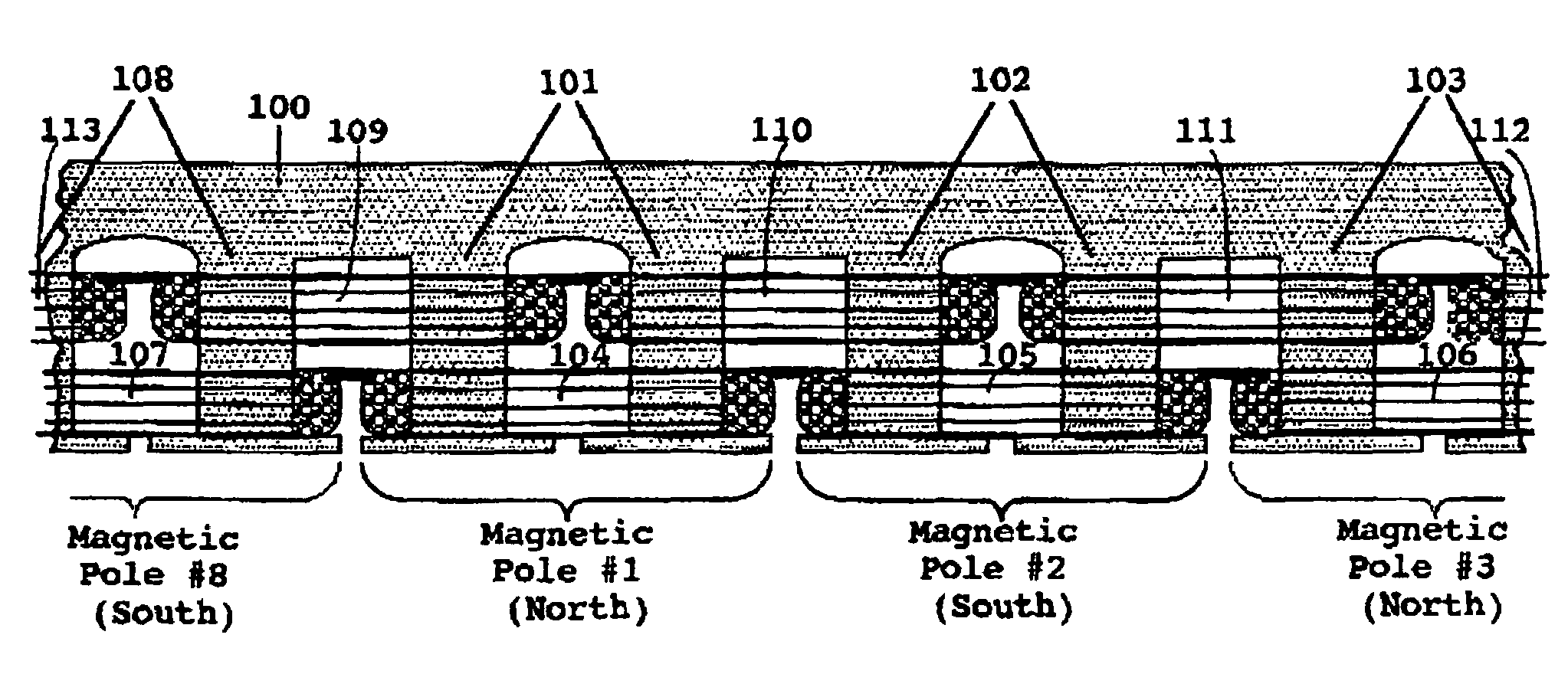
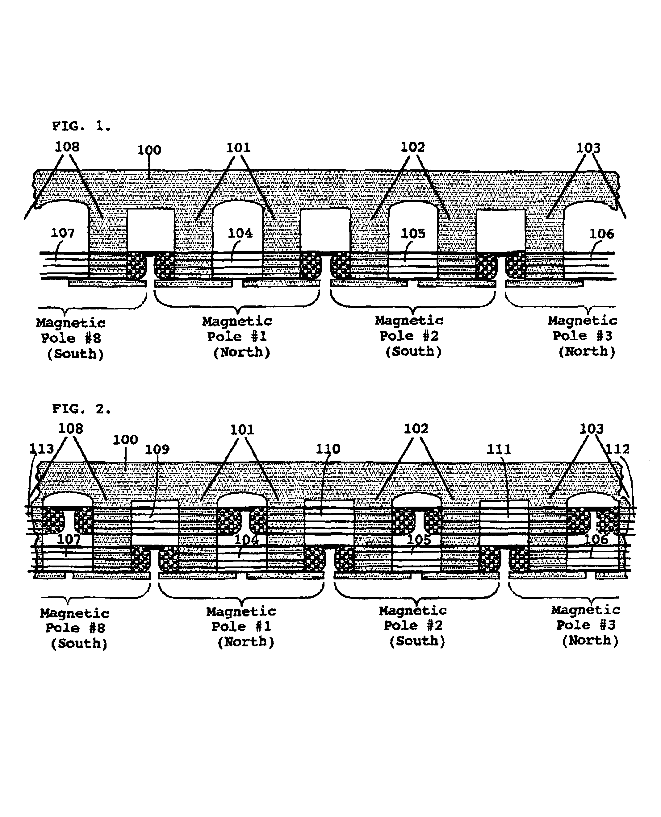
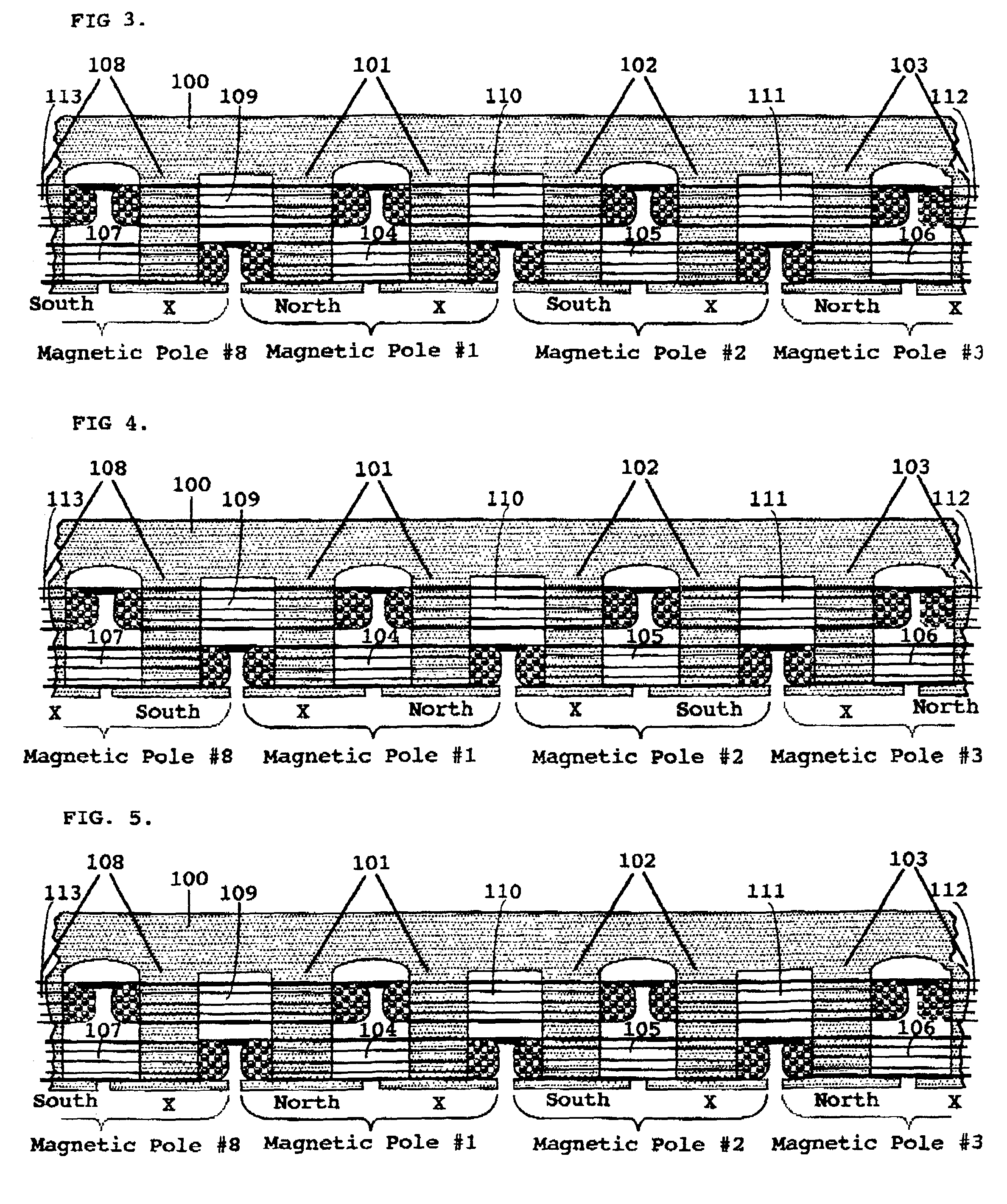
[0029]FIG. 1 is a diagrammatic view of a portion of the Split-Pole Field-Match Motor stator 100, which, in its entirety, would be an eight (8) pole stator, in which only the DC stator coils 104, 105, 106, 107 are shown wrapped around the split-poles 101 and 102 (fully shown) and 103 and 108 (partially shown). As illustrated, split-pole 101 is designated as magnetic-pole #1 and will always have a north field being induced into both halves of the pole by the DC coil 104. This means that the two salient protrusions which make up the two halves of split-pole 101 form a single magnetic pole which will always have a north field on the face of one of its halves. Split-pole 102 is designated as magnetic-pole #2 and always has a south field being induced into both halves of the pole by the DC coil 105. This means that the two salient protrusions which make up the two halves of split-pole 102 form a single magnetic pole which will always have a south field on the face of one of its halves. Th...


PUM


Abstract

An electric motor having a plurality of rotor and stator poles, the poles of one element being alternately polarized and neutralized due to the use of direct current and alternating current windings on each pole. The poles of like current are connected in series, and the direct current poles are energized in synchronization with the alternating current poles.

Description

FIELD OF THE INVENTION[0001]The invention pertains to electric motors having a plurality of magnetic poles wherein the poles are alternately polarized and neutralized to produce rotation of a motor rotor.STATE OF RELATED ART[0002]It is commonly known that a magnet pole or a ferrite pole with an energized direct current (DC) coil around it will only allow flux which is in-phase (with the same magnetic orientation) to travel through the pole. Flux which has an opposite magnetic orientation will be rejected unless it is strong enough to overpower and reverse the permanent magnet pole's orientation or to “capture” and reorient the ferrite pole and align it against the DC coil. According to traditional magnetic theory, each magnet or DC electromagnet will only pass flux in one direction, from the south pole through to the north pole. A magnet or DC electromagnet will not allow flux to pass from the north pole through to the south pole.[0003]Further, it is also known that if two coils of ...

Claims


Application Information

Patent Timeline
Patent Type & Authority Patents(United States)
IPC IPC(8): H02K1/00
CPCH02K29/03H02P25/08H02P1/163H02K1/246H02K19/103H02K19/24H02K21/44
Inventor DURHAM, GARY L.DURHAM, HAROLD STEPHEN
Owner TRI SEVEN RES
Why Eureka
Try Eureka