
Gas-powered tip-jet-driven compound VTOL aircraft

a technology of compound vertical takeoff and landing and tip-jet, which is applied in the direction of rotors, vehicles, propellers, etc., can solve the problems of poor economic operation and maintenance, high cost, and high cost of shaft driven rotors, and achieves low cost, high thrust augmentation ratio, and high speed

Inactive Publication Date: 2007-10-02
FLANIGAN KENNETH WARREN
View PDF17 Cites 58 Cited by
  • Summary
  • Abstract
  • Description
  • Claims
  • Application Information

AI Technical Summary

Benefits of technology

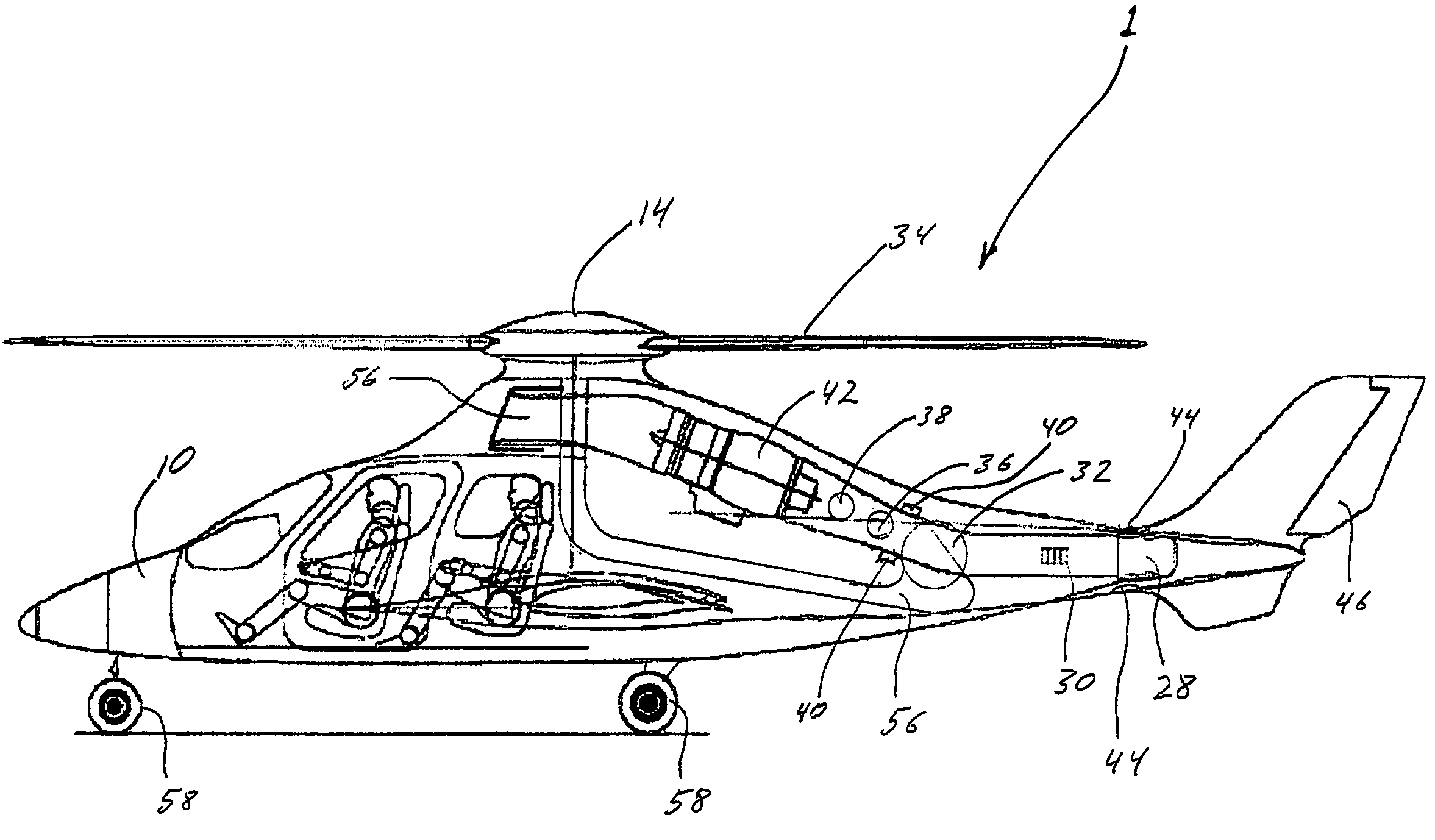
[0017]Unlike the cyclic rotor control and the abrupt change from rotor to propeller power used on the McDonnell XV-1 to gain forward speed, soon after leaving the ground certain embodiments of the present invention gradually redirect some of the compressed gas from the rotor tip-jets to a jet exhaust nozzle to provide forward thrust. Compressed gas is still provided to the tip-jets for climbing prior to aircraft forward speed being sufficient for the wings to sustain the aircraft. This unique design provides a very smooth transition to forward flight because there is no abrupt change from one mode to another. Rather, the main gas valve gradually transfers thrust from the tip-jets to the jet exhaust.
[0018]By using a compressed gas driven rotor, certain embodiments of the present invention implement multiple-flow thrust generators, which can provide high thrust augmentation ratios. Coupled with a small fixed wing and a means of managing the rotor through many dynamic effects as the rotor passes into mu-1 and beyond, certain embodiments of the present invention can achieve very high speeds for an aircraft with a rotary-wing. The preferred embodiment of the present invention represents a compound VTOL aircraft that is faster, much lighter, much less costly, much less complex and more efficient than is presently known in the art.

Problems solved by technology

The field of compound aircraft can be broken down into three broad categories relative to their rotors:4. Shaft driven rotors, which employ the use of high-maintenance mechanical drive systems, are often massive, complex, expensive, and inefficient.
They cause accompanying aircraft to be expensive, have poor economy of operation and maintenance, poor empty-weight fraction, poor range, poor performance, and still other factors that will be discussed in more detail below.Typical of the shaft driven compound aircraft is the aircraft disclosed in U.S. Pat. No. 3,155,341, by P. F. Girard. Another is disclosed in U.S. Pat. No. 5,174,523, which discusses “engine shaft power output control.” Both include heavy, expensive gearboxes and attendant shafting.
The big disadvantages of the autogyro types are the lack of hovering ability, agility, responsiveness, room for error, and limited freedom of choice in VTOL maneuvers.
This group is tricky and unforgiving to land, as rotor rpm can be difficult to manage.
This adds more weight and expense to the aircraft, and, in addition, necessitates an anti-torque device.6. A third category includes VTOL aircraft capable of flying vertically via gas-powered tip-jet-driven rotors.
It did not have the capability to exceed mu-1, however.
The lifting hardware makes the aircraft inefficient in forward flight.
With no fixed wing, this aircraft's forward speed is limited by advancing tip speed and / or retreating blade stall.
The plenum will not be as efficient as a high aspect ratio wing, and it will act as a large reservoir for the compressed gas that will slow the response time when the pilot calls for increased or decreased rotor rpm.
The accompanying wing does not totally sustain the aircraft even at top speed.

Method used


Image

  • Gas-powered tip-jet-driven compound VTOL aircraft
  • Gas-powered tip-jet-driven compound VTOL aircraft
  • Gas-powered tip-jet-driven compound VTOL aircraft

Examples


Embodiment Construction

[0031]Tip-jet driven rotors can be termed multiple-flow thrust generators. J. V. Foa in Elements of Flight Propulsion (published by Wiley and Sons) defines a multiple-flow thrust generator as “one in which various aggregates of the working fluid undergo different cycles.” (He refers here to different thermal cycles.) Examples are: a) turbofans; b) turboprops; c) ducted engines; and d) tip-jet-driven propellers and rotors.

[0032]Of all of the various means of applying direct lift to a craft, none can compete with a well designed multiple-flow thrust generator in terms of energy applied. This is due to a little understood fact that this type of thrust generator provides “thrust-augmentation.” Foa defines thrust-augmentation as “an increase in thrust at no extra cost in energy input.” He remarks that a jet-driven propeller provides one of the most striking illustrations of the thrust-augmentation.

[0033]By way of example, a quarter-scale model (rotor diameter of 5.65 feet) of a tip-jet r...


PUM


Abstract

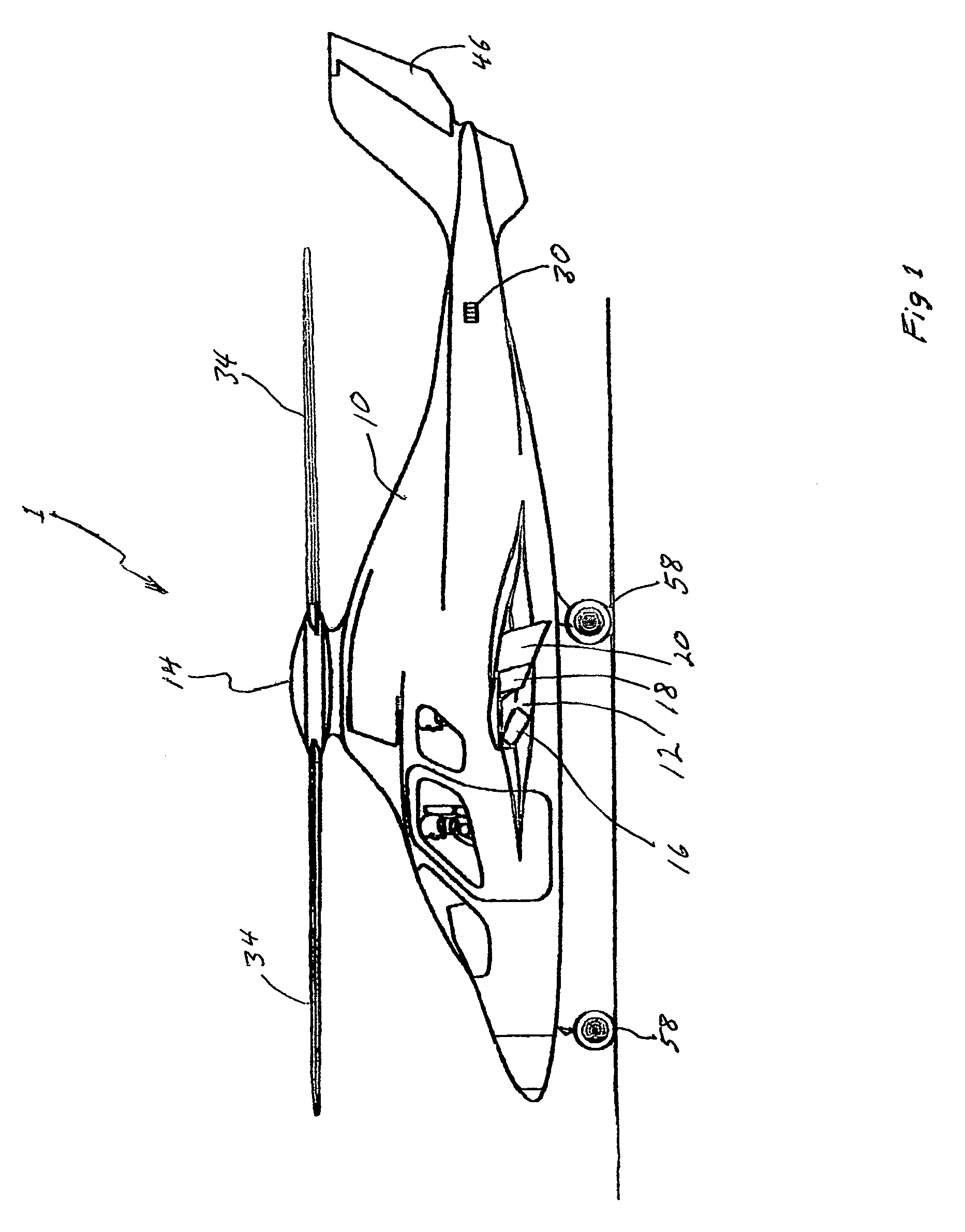
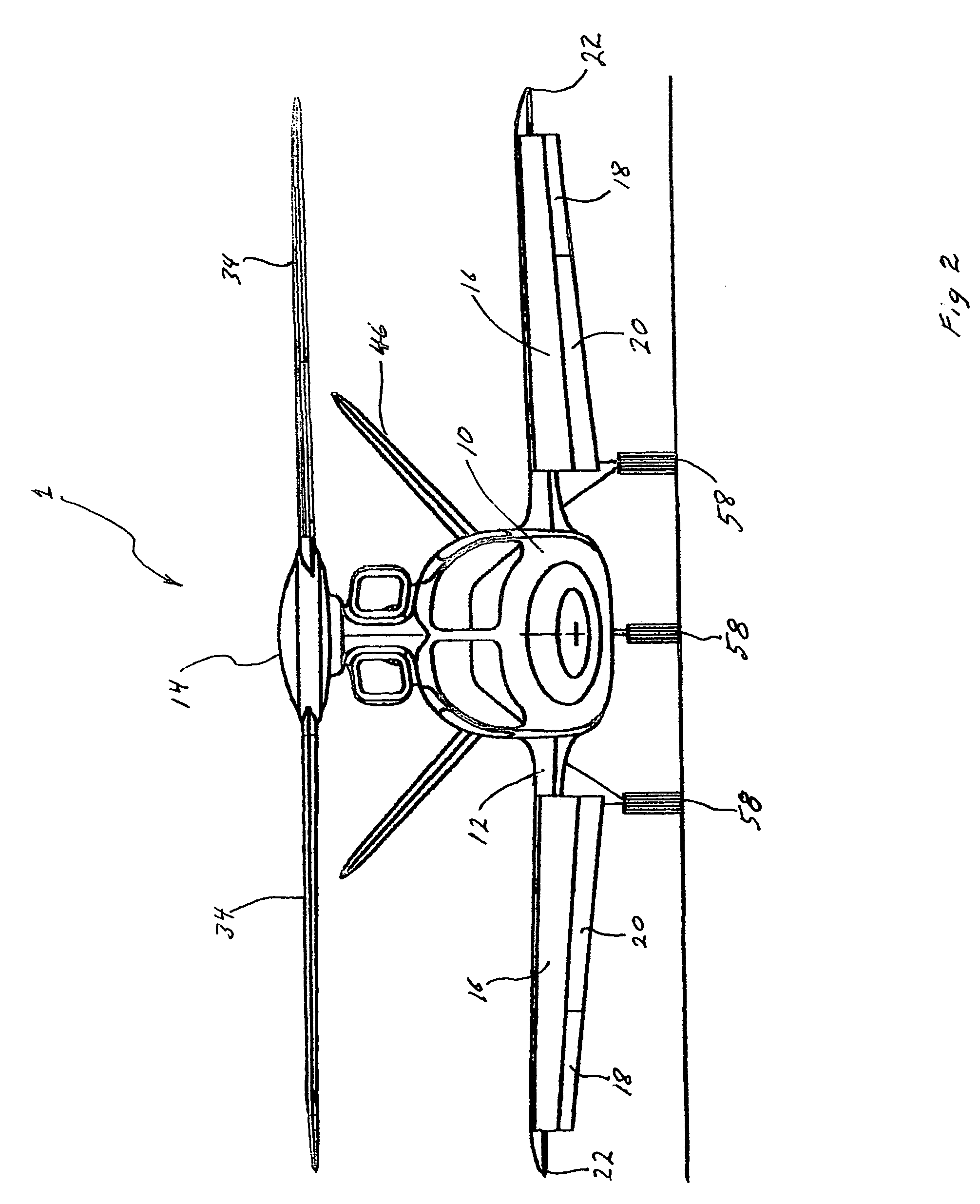
A compound Vertical TakeOff and Landing (VTOL) aircraft. In a specific embodiment, the VTOL aircraft includes a gas-powered tip-jet driven rotary-wing and a fixed-wing that is capable of providing necessary lift to the aircraft during certain forward-flight regimes so that lift from the rotary-wing is not required. This enables slowing of the rotor, thereby reducing drag during forward flight and enabling flight above and below mu-1. Valves and accompanying ducting are employed to control compressed gas flow to the rotary-wing. Various reaction jets are employed for attitude control during VTOL and transition operations. The aircraft further includes a jet exhaust nozzle to provide forward thrust to facilitate forward flight.

Description

CROSS-REFERENCE TO RELATED APPLICATION[0001]This application claims the benefit of U.S. Provisional Patent Application Ser. No. 60 / 547,025, filed on Feb. 23, 2004, by the present inventor.BACKGROUND OF THE INVENTIONField of Invention[0002]This invention relates to compound Vertical TakeOff and Landing (VTOL) aircraft utilizing a gas driven rotor.BACKGROUND OF THE INVENTION[0003]In around the year 100 BC, Hero of Alexandria discovered the reaction engine with his aeolipile experiment. Then the Wright brothers introduced powered flight in 1903, and in 1910 Henri Marie Coanda married the two together to fly the first jet-propelled airplane. In 1955 the McDonnell XV-1 tip-jet autogyro made its record-breaking flight.[0004]With man's desire for aircraft that would use less runway coincident with flying faster, safer and easier handling, he has created many different types of VTOL, SVTOL or compound aircraft including helicopters, autogyros, tilt-rotors, tip-jets, convertiplanes, gyrodyne...

Claims


Application Information

Patent Timeline
Patent Type & Authority Patents(United States)
IPC IPC(8): B64C27/18
CPCB64C27/18B64C27/26B64C27/24
Inventor FLANIGAN, KENNETH WARREN
Owner FLANIGAN KENNETH WARREN
Learn More