Forward (Upstream) Folding Rotor for a Vertical or Short Take-Off and Landing (V/STOL) Aircraft

a vertical or short take-off and landing aircraft and forward (upstream) technology, applied in the direction of rotocraft, vertical landing/take-off aircraft, propellers, etc., can solve the problems of hydraulic actuators that are less reliable, prone to wear and leakage, and require additional hardening and lengthening of pylons for folding rotors. to achieve the effect of reducing or eliminating cg shift, reducing drag on the wings, and increasing the capability of til

Inactive Publication Date: 2010-03-25
SAMBELL KENNETH WILLIAM
View PDF14 Cites 104 Cited by
  • Summary
  • Abstract
  • Description
  • Claims
  • Application Information

AI Technical Summary

Benefits of technology

[0012]This invention discloses a further attempt to increase the capabilities of the tilt-rotor concept. Specifically, this invention discloses a system which will allow the aircraft to use rotary thrust for vertical take-off and sub-fixed wing stall speed and jet engines for speeds not only above fixed wing stall speed but also speeds above those possible with conventional rotary or propeller thrust. This invention improves over prior art

Problems solved by technology

First, the aft folding of the rotors would cause a large center of gravity shift toward the rear of the craft which would impose additional control requirements and possible instabilities.
Second, the aft folding rotors would require additional hardening and lengthening of the pylons to prevent

Method used


Image

  • Forward (Upstream) Folding Rotor for a Vertical or Short Take-Off and Landing (V/STOL) Aircraft
  • Forward (Upstream) Folding Rotor for a Vertical or Short Take-Off and Landing (V/STOL) Aircraft
  • Forward (Upstream) Folding Rotor for a Vertical or Short Take-Off and Landing (V/STOL) Aircraft

Examples


Embodiment Construction

[0021]This concept is a member of the well known Tilt-Rotor family of vertical / short take-off aircraft. It is a variant of the folding tilt-rotor aircraft of Ref. 1, of which I am co-inventor.

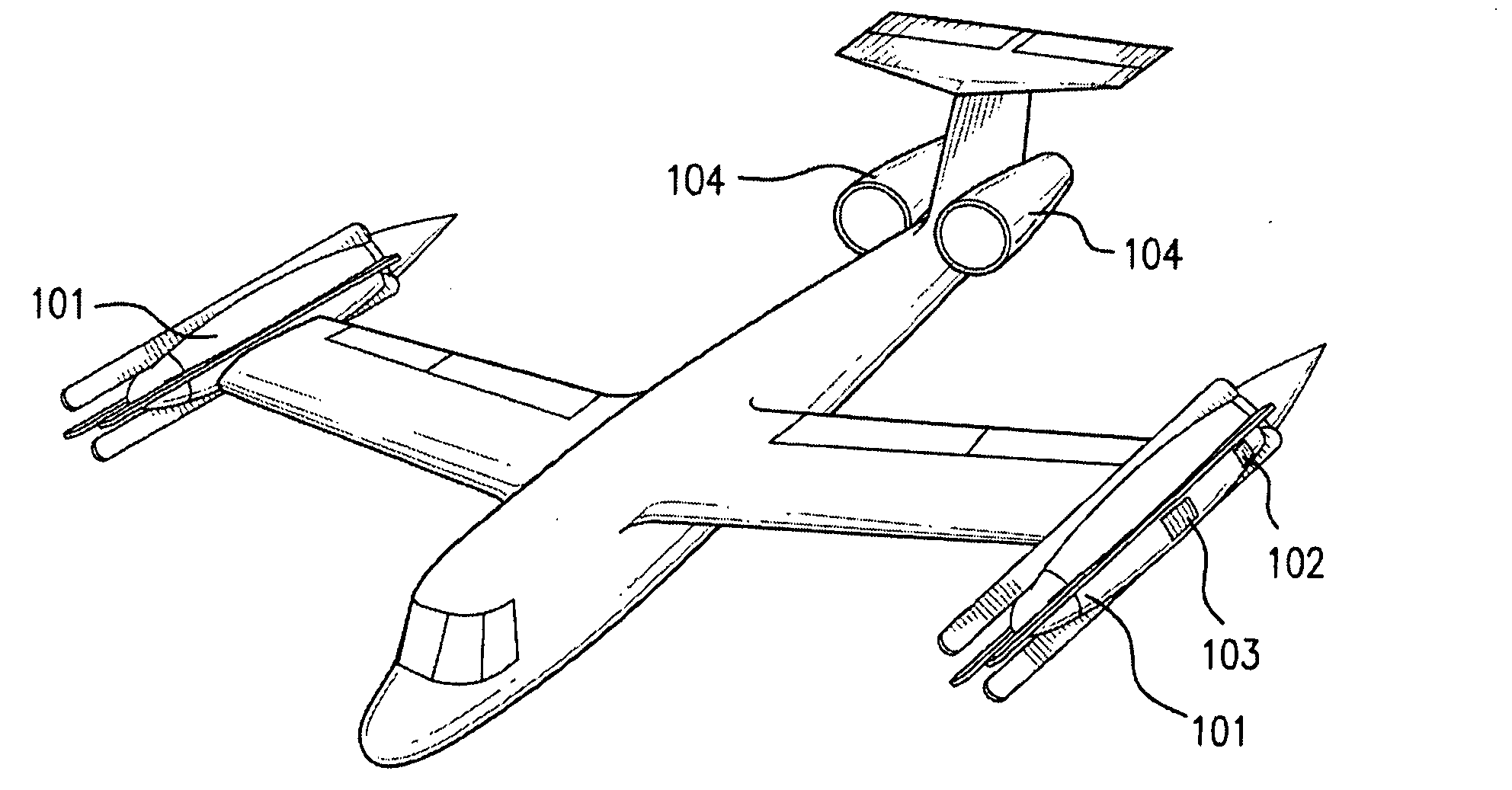
A. TAKE-OFF CONFIGURATION FIG. 1

[0022]Rotors (4 bladed in this embodiment) are mounted on tip-pods 101 at the wing-tips, inter-connected by the usual shaft-drive. Rotor axes can tilt from 30 deg. forward of vertical to 90 deg. aft of vertical. Rotors are driven by shaft-engines mounted in the tip-pods. Inlet air enters thru streamlined louvers 102. Exhaust air exits thru the lower louvers 103. These louvers are closed in cruise flight into a low-drag streamlined position.

Additional engines 104 are mounted at the rear of the fuselage. These engines are used during transition and cruise flight and are at idle thrust during vertical take-off.

B. CRUISE CONFIGURATION FIG. 2

[0023]The rotor blades are folded into the tip-pods and locked securely. The shaft-engines are stopped and all louvers closed. T...


PUM


Abstract

This is an improvement of the 1968 Trailing Rotor V/STOL aircraft (Ref. 1). Rotors are mounted on wing-tip pods which can be tilted from the vertical to the horizontal aft position. Rotors are then stopped in the axial-flow condition and indexed to an azimuth position, aft of the wing trailing-edge. Rotor blades are then folded forward (blade-tips upstream of rotor-hubs) and locked into grooves in the tip-pods.
The main improvements over Ref. 1 are: a smaller shift of center-of-gravity during transition to cruise mode, and an easier task of locking blades into the tip-pods.
The main feature of the autorotative aft rotor tilt is that a soft-inplane rotor can be used, which reduces rotor weight. The blade-folding axis is also the blade-flapping axis.
The autorotative mode is used frequently by helicopters during descent. It has been found to be a good, stable mode with rpm-stability. During aft tilt on the UFR, the rotors provide pitching stability to the airframe. During stopping of the rotor, the stability of the autorotating rotor eases the task of passing thru rotor resonance.
Also, the wing can be swept back, which is desirable for 400 kt. cruise speeds and can be used for external stores such as fuel and weapons.

Description

CROSS-REFERENCE TO RELATED APPLICATIONS[0001]Ref. 13,404,85210 / 1968Sambell et alRef. 25,085,315 2 / 1992SambellSTATEMENT REGARDING FEDERALLY SPONSORED RESEARCH OR DEVELOPMENT[0002]Not applicableREFERENCE TO SEQUENCE LISTING, A TABLE, OR A COMPUTER PROGRAM LISTING COMPACT DISC APPENDIX[0003]Not applicableBACKGROUND OF THE INVENTION[0004]This invention is a member of the well known Tilt-Rotor family of vertical or short take-off and landing (V / STOL) aircraft. It is a variant of the folding tilt-rotor aircraft of Ref. 1, of which I am a co-inventor. The most successful version of this family of aircraft is the Bell Helicopter Osprey (V-22) manufactured by Bell Helicopter. The V-22 has proved the viability of the concept of using rotary thrust for vertical take-off and then tilting of the rotors forward to provide forward / horizontal thrust in combination with fixed wing lift. Traditionally, helicopter aircraft cannot travel at speeds exceeding 180kt. The V-22 specifies a top speed around ...

Claims


Application Information

Patent Timeline
IPC IPC(8): B64C27/22B64C29/00
CPCB64C11/28B64C29/0033B64C27/50
Inventor SAMBELL, KENNETH WILLIAM
Owner SAMBELL KENNETH WILLIAM
Why Eureka
Try Eureka