
Autonomic embedded computing "dynamic storage subsystem morphing"

a technology of embedded computing and dynamic storage, applied in the direction of electric programme control, program control, instruments, etc., can solve the problems of electronic system failures, vehicle defects throughout the vehicle lifecycle are already dominated by electronic system failures, and normal dominance of potential vehicle defects, so as to avoid higher costs, improve error handling, and reduce refresh rate

Inactive Publication Date: 2007-09-25
IBM CORP
View PDF5 Cites 13 Cited by
  • Summary
  • Abstract
  • Description
  • Claims
  • Application Information

AI Technical Summary

Benefits of technology

The present invention provides a method for operating a plurality of embedded systems with multiple application-specific electronic control units (ECUs) that can share resources to avoid high costs in case of breakdowns. The method involves designating one of the ECUs as a "donor" ECU with a larger amount of storage and processing resources, and in case of a breakdown of a non-donor ECU, the donor ECU takes over its functions. The method also includes a mechanism for accessing the shared storage area of the non-donor ECU by using transformed addresses, which allows for efficient use of the shared resources. The invention also provides improvements for both single-housing and multi-housing designs of the embedded system.

Problems solved by technology

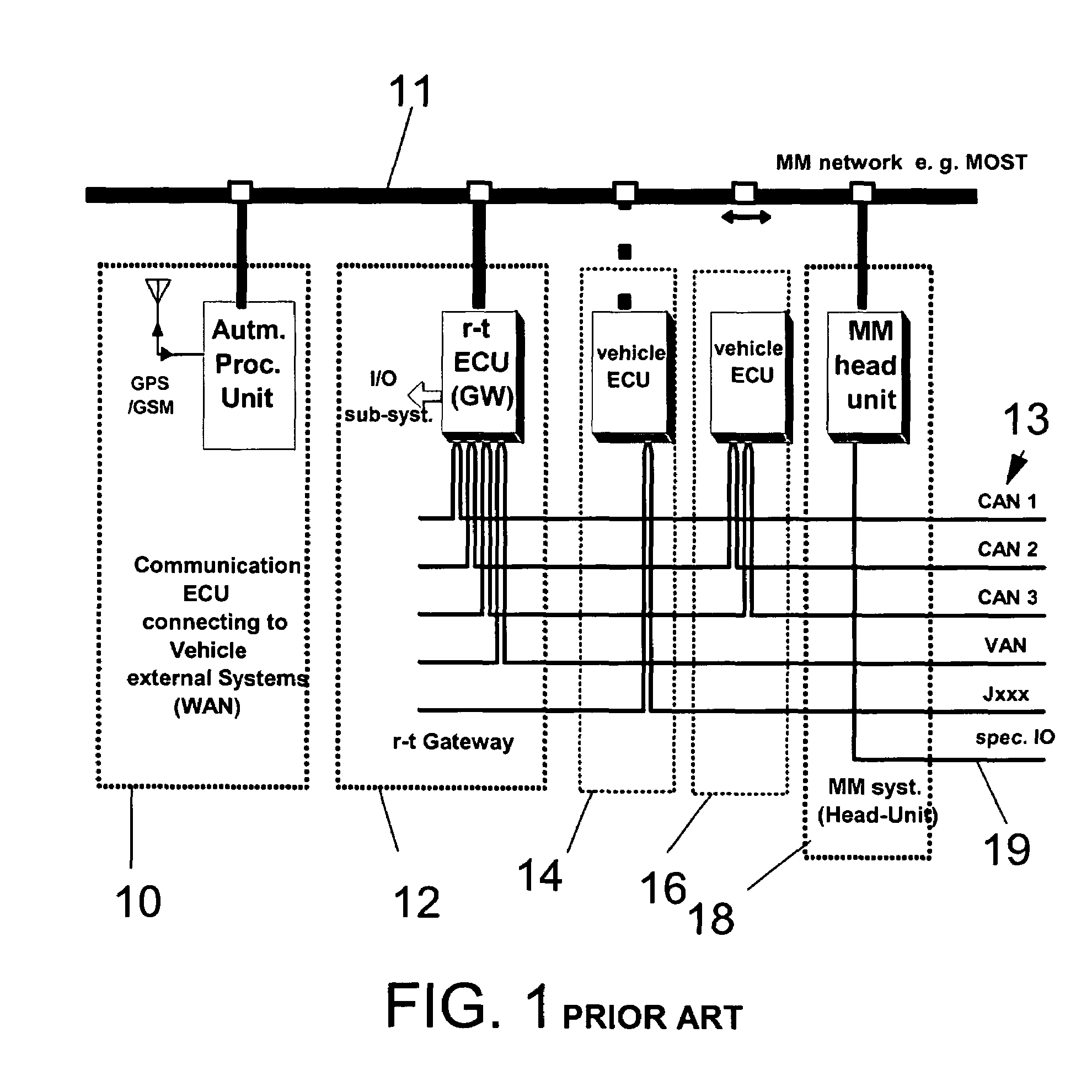
Previously—typical to the mechanical nature of automobiles—the potential vehicle defects were normally dominated by mechanical wear out and associated malfunctions.
Due to the described increase of electronics complexity and electronic component volume—the nature of vehicle failures is changing.
As documented in vehicle breakdown statistics, the vehicle defects throughout the vehicle lifecycle is already dominated by electronic system failures.
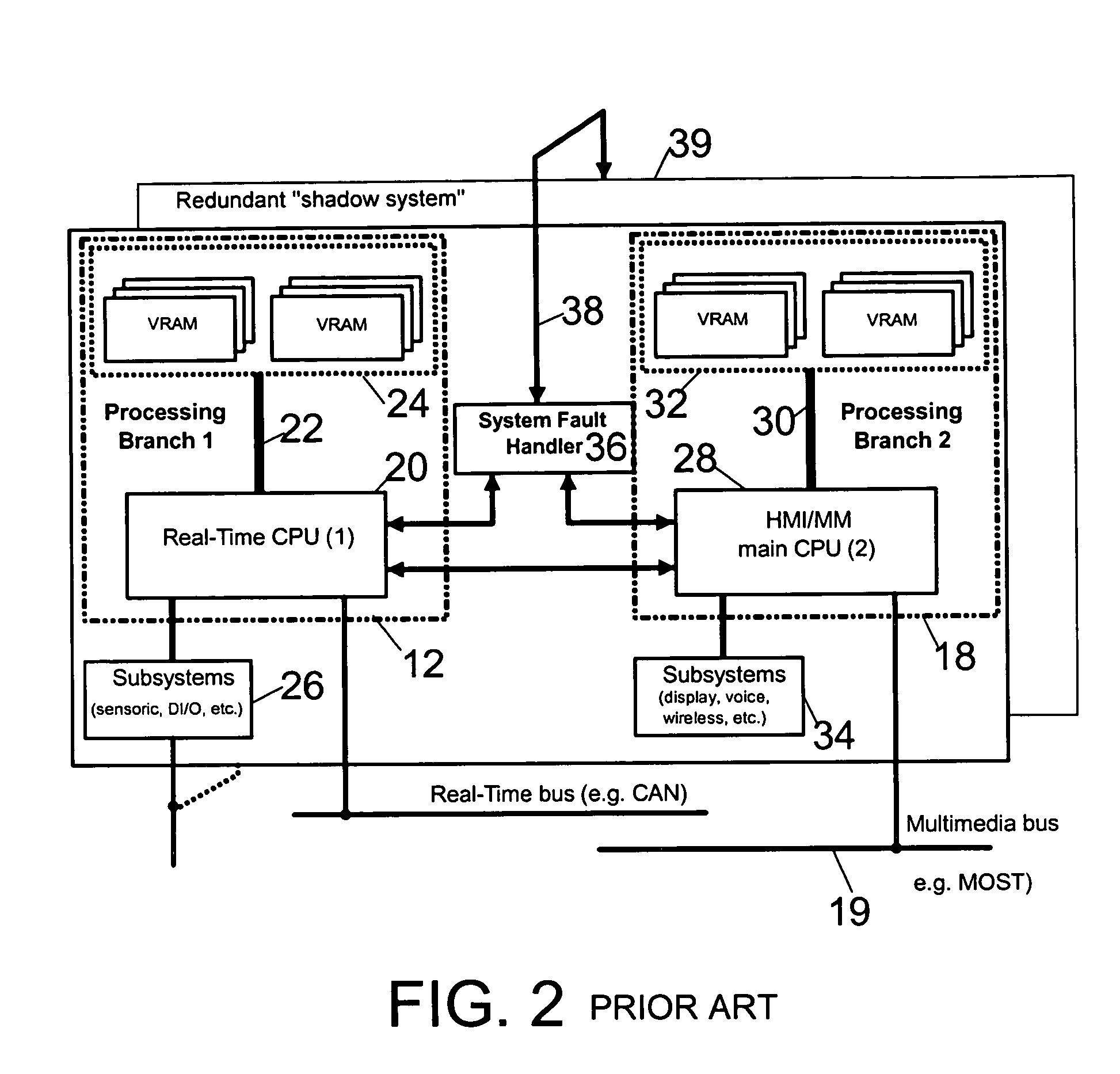
In case of a CPU failure, the entire processing-branch related functionality will be lost, and in case of a storage subsystem failure, the entire processing-branch-related functionality will be lost.
The drawbacks of this redundancy are:high system costs,increased physical dimensions in size and mass,increased power dissipation,increased electronic volume—and therefore increased potential for subsequent failures.

Method used


Image

  • Autonomic embedded computing "dynamic storage subsystem morphing"
  • Autonomic embedded computing "dynamic storage subsystem morphing"
  • Autonomic embedded computing "dynamic storage subsystem morphing"

Examples


Embodiment Construction

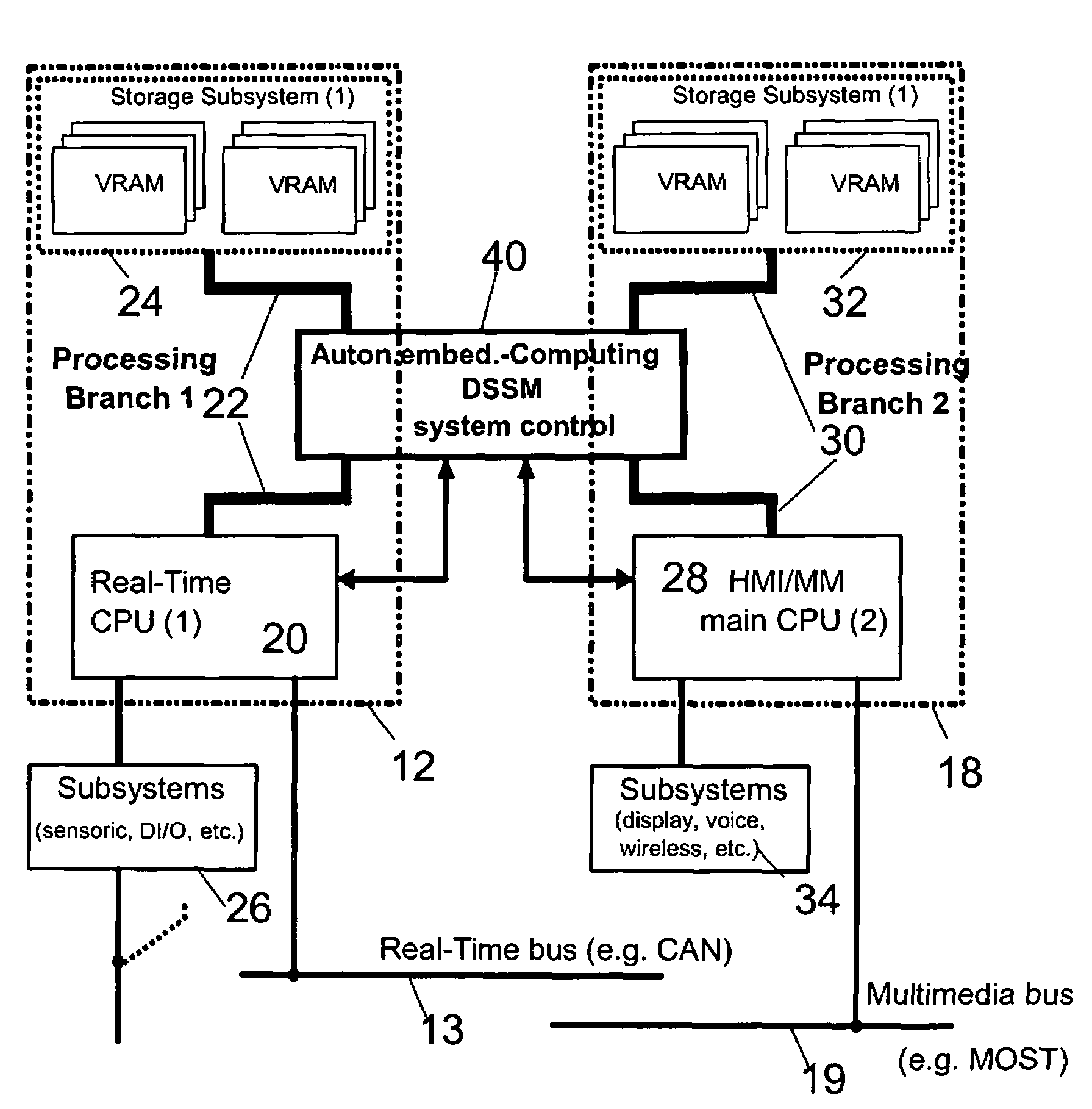
[0066]With general reference to the figures and with special reference now to FIG. 3 a preferred implementation of the before-mentioned automotive telematics unit is described in more detail as a specific embodiment of the present invention, in which the donor-ECU is the multimedia ECU 18, and only one single non-donor-ECU is applied, i.e. a real-time ECU 12. It should be noted, however, that this embodiment can be easily extended to comprise more than one real-time ECU and may modified broadly without departing from the very scope of the invention, eg by providing also some donor functionality or attributes within the real- time ECU 12. The limitation is thus simply caused for sake of increased clarity of the core ideas of the present invention.

[0067]As reveals from FIG. 3, according to this specific, inventive embodiment a circuit 40 is provided which replaces. the system fault handler 36 provided in prior art, i.e. which incorporates the basic logic of it and, additionally includ...


PUM


Abstract

A Dynamic Storage Subsystem Morphing (DSSM) mechanism (40) is connected to a plurality of storage subsystem resources, which reserve some storage area each non-donor ECU (12), ready for a “slot-down / up” access by a respective non-donor ECU having a storage subsystem (24) breakdown. The slot-down process enables the use of a high physical address range by the non-donor processor provided with addressing capabilities sufficient only for addressing lower ranges.

Description

TECHNICAL FIELD OF THE INVENTION[0001]The present invention relates to the field of embedded processing systems and to autonomic embedded computing solutions, and in particular to embedded processing system covering a plurality of technical applications, the operative functions of which are performed with a respective plurality of application-specific Electronic Control Units (ECU) applying general loosely coupled multiprocessing.BACKGROUND OF THE INVENTION[0002]The typical application fields of embedded processing systems and Electronic Control Units (ECUs) covered by the proposed invention is covering the major embedded systems market segments:[0003]1. Automotive ECUs, Multi-Media Units, Telematics-Units[0004]2. Industrial Control Units (machinery tool control, manufacturing-line control units)[0005]3. Home-Appliance Electronic Control Units[0006]4. Commercial and Industrial Diagnostics Equipment tools.[0007]The term “embedded system” is to be understood as any computing system or...

Claims


Application Information

Patent Timeline
Patent Type & Authority Patents(United States)
IPC IPC(8): G06F11/00H04L1/22
CPCH04L1/22
Inventor STAIGER, DIETER
Owner IBM CORP
Learn More