
Developing apparatus

a technology of developing apparatus and developing chamber, which is applied in the field of developing apparatus, can solve the problems of increasing fogging, reducing the transfer efficiency of halftone pattern images, so-called white spots, etc., and achieves the effects of reducing fogging, reducing development failures, and reducing black-lined images

Inactive Publication Date: 2007-09-11
CANON KK
View PDF11 Cites 10 Cited by
  • Summary
  • Abstract
  • Description
  • Claims
  • Application Information

AI Technical Summary

Benefits of technology

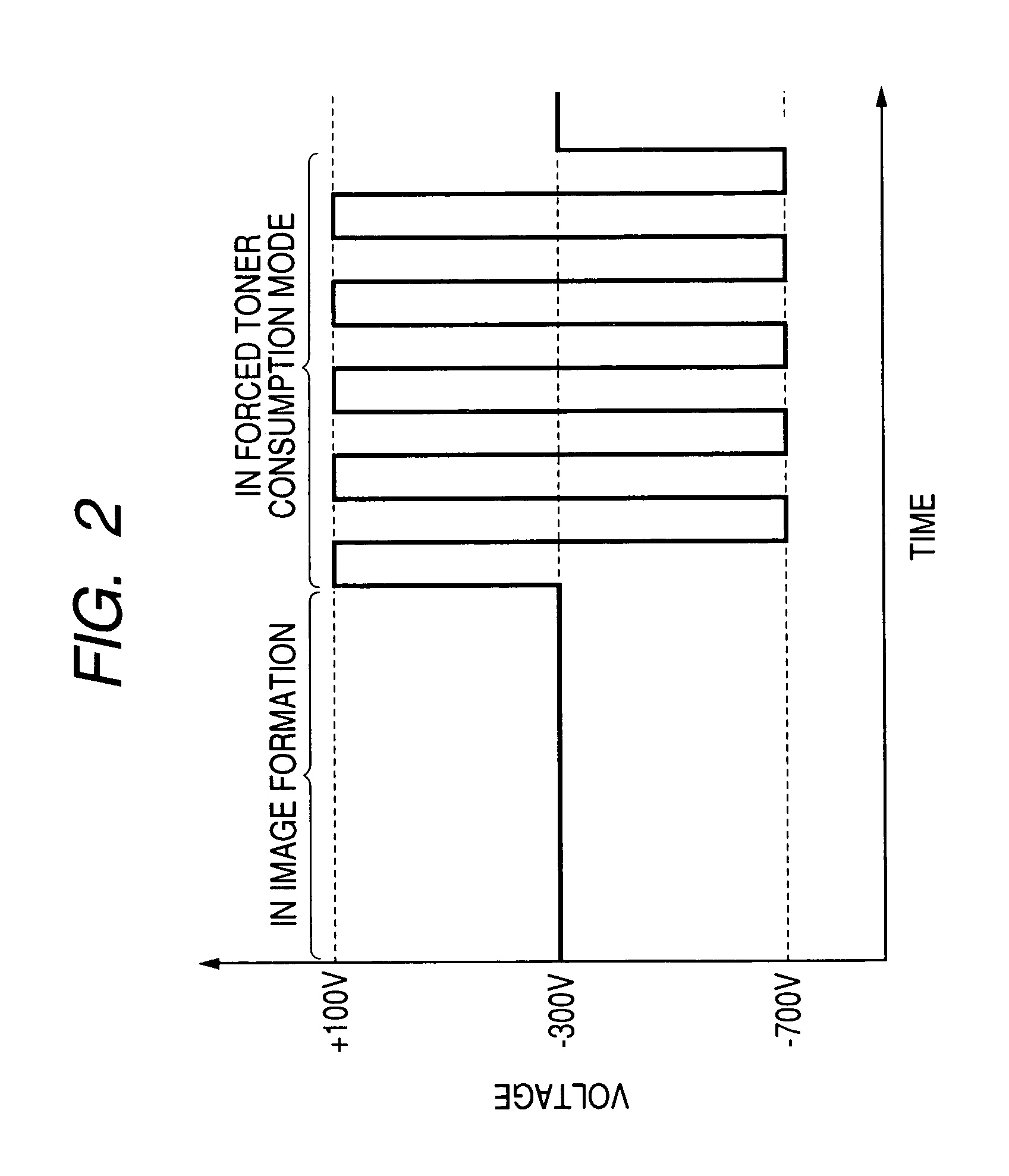
The forced toner consumption mode effectively reduces fogging, white-spots-image, and black-lined images in halftone patterns, maintaining image quality and extending the service life of the developing apparatus by periodically removing toner deposits and preventing fusion-bonding.

Problems solved by technology

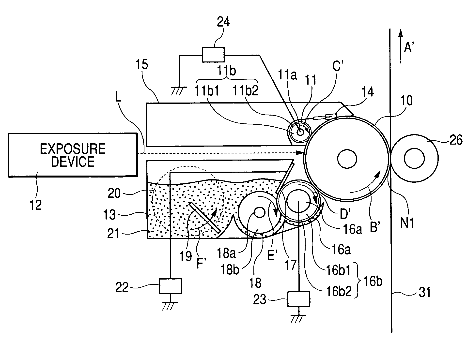
When a remaining amount of the toner is reduced, the toner in the developing container 20 shows an increase in the proportion of the toner of inferior developing property and causes deterioration of the toner itself, thereby resulting in an increased fogging in a latter part of a printing durability test, a decrease in the transfer efficiency in an image of a halftone pattern, or in a so-called white-spots-image caused by defective transfer in many small areas on an image.
However, even with such forced toner consumption by the solid image printing at every predetermined number of prints, the toner of inferior developing property may still not be transferred onto the photosensitive drum 10 but remain on the developing roller 10 in the developing step, so that the toner of inferior developing property cannot be sufficiently transferred to the photosensitive drum 10 thereby resulting in an increase of fogging in a latter part of the service life of the developing apparatus or a white-spots-image in a halftone patterned image.

Method used


Image

  • Developing apparatus
  • Developing apparatus
  • Developing apparatus

Examples


example 1

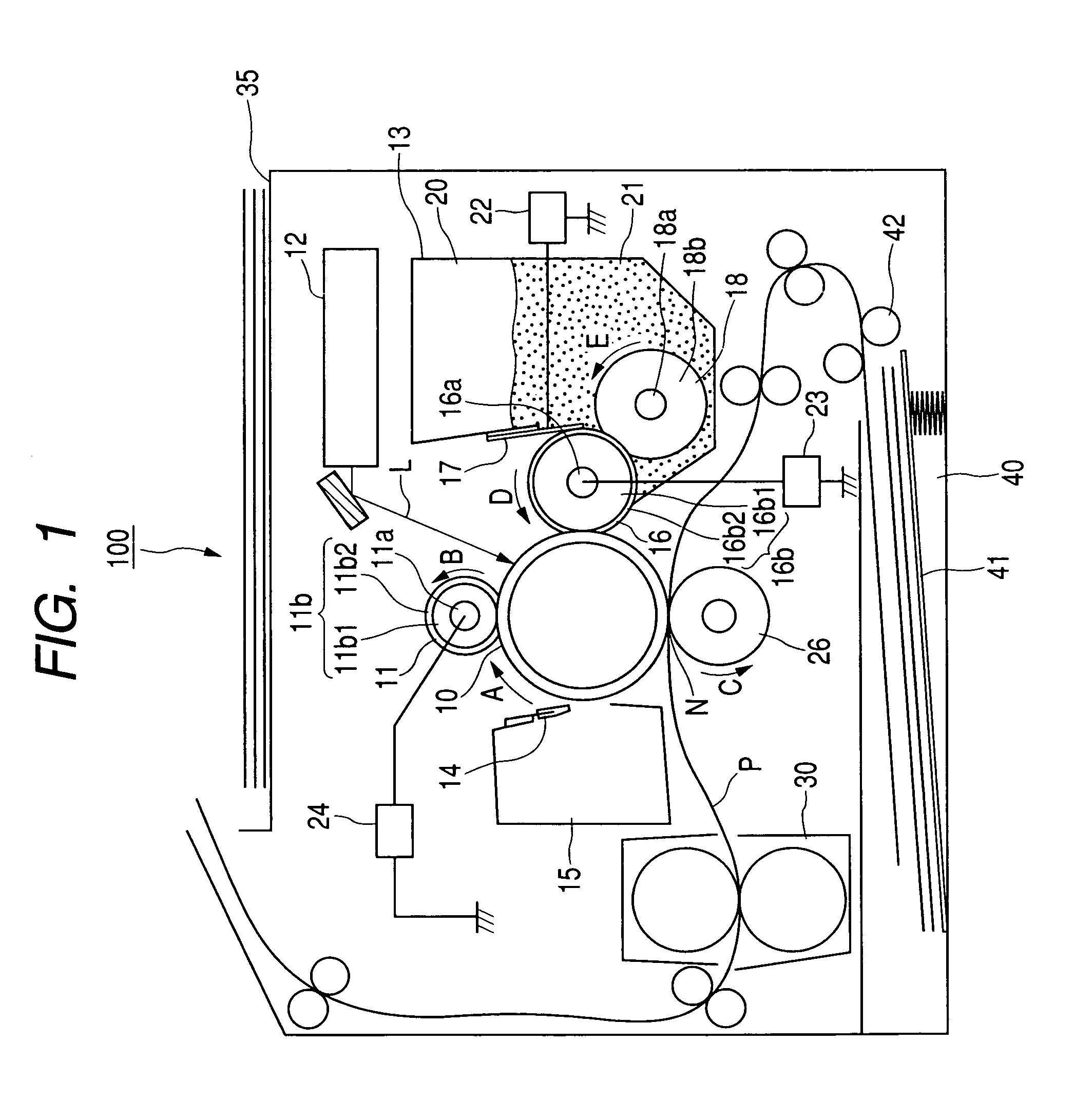
[0028]FIG. 1 is a schematic cross-sectional view of an example of an image forming apparatus of the present invention. An image forming apparatus 100 of the present example is capable of forming an image on a recording material such as a recording paper, an OHP sheet, a cloth, etc. by an electrophotographic process, according to an image information signal from an external host equipment such as a personal computer, connected communicably with a main body of the apparatus. Components equivalent in function or configuration to those in a conventional image forming apparatus shown in FIG. 7 are represented by same numbers.

[0029]The image forming apparatus 100 of the present example is provided with a drum-shaped electrophotographic photosensitive member (photosensitive drum) 10, serving as an image bearing member. In the present example, the photosensitive drum 10 is formed by coating an external periphery of an aluminum cylinder of a diameter of 30 mm with an organic photoconductor (...

example 2

[0066]In the following there will be explained another example of the developing apparatus of the present invention. An image forming apparatus of this example is a color image forming apparatus, capable of forming a full-color image by an electrophotographic process, according to an image information signal from an external host equipment such as a personal computer, connected communicably with a main body of the apparatus.

[0067]FIG. 5 is a schematic cross-sectional view of the color image forming apparatus 200 of the present example. The image forming apparatus 200 is provided, as image forming means, with first to fourth image forming portions (image forming units) PY, PM, PC, PBk for respectively forming images of yellow (Y), magenta (M), cyan (C) and black (Bk). The image forming apparatus 200 of the present example is a full-color printer of a so-called tandem type, in which the four image forming portions PY, PM, PC and PBk are arranged in parallel, along an intermediate tran...


PUM


Abstract

A developing apparatus including a developer carrying member for carrying a developer for developing an electrostatic image, formed on an image bearing member, with the developer, a developer regulating member for regulating the developer carried on the developer carrying member, and an oscillating electric field forming device which forms an oscillating electric field between the developer carrying member and the developer regulating member, wherein a developer consuming operation is executed for consuming the developer from the developer carrying member to an image non-forming area of the image bearing member and a period of forming the oscillating electric field is provided in the operation.

Description

BACKGROUND OF THE INVENTION[0001]1. Field of the Invention[0002]The present invention relates to a developing apparatus having a developer carrying member and a developer regulating member, and more particularly to a developing apparatus adapted for use in an image forming apparatus utilizing an electrophotographic process or an electrostatic recording process such as a copying apparatus, a printer, a facsimile apparatus, etc.[0003]2. Description of the Related Art[0004]In an image forming apparatus of electrophotographic process, a recorded image is formed by charging an image bearing member, then exposing it according to image information to form an electrostatic image, supplying the image bearing member with a developer according to such electrostatic image thereby forming a developer image, then transferring such a developer image by transfer means onto a recording material (transfer member) such as a recording sheet, an OHP sheet or a cloth, and fixing it by fixing means.[0005]...

Claims


Application Information

Patent Timeline
Patent Type & Authority Patents(United States)
IPC IPC(8): G03G15/08G03G15/01G03G15/00G03G15/06G03G21/14
CPCG03G15/0812
Inventor HASHIMOTO, KAZUNORI
Owner CANON KK
Learn More