
Image forming apparatus and treatment thereof

a technology of image forming apparatus and forming patch, which is applied in the direction of electrographic process apparatus, instruments, optics, etc., can solve the problems of insufficient consumption of toner, and insufficient discharge of toner by toner discharge patch, so as to solve the problem of image quality defect, prevent the effect of reducing the image quality associated with the shortage of toner density

Active Publication Date: 2007-09-11
FUJIFILM BUSINESS INNOVATION CORP
View PDF2 Cites 24 Cited by
  • Summary
  • Abstract
  • Description
  • Claims
  • Application Information

AI Technical Summary

Benefits of technology

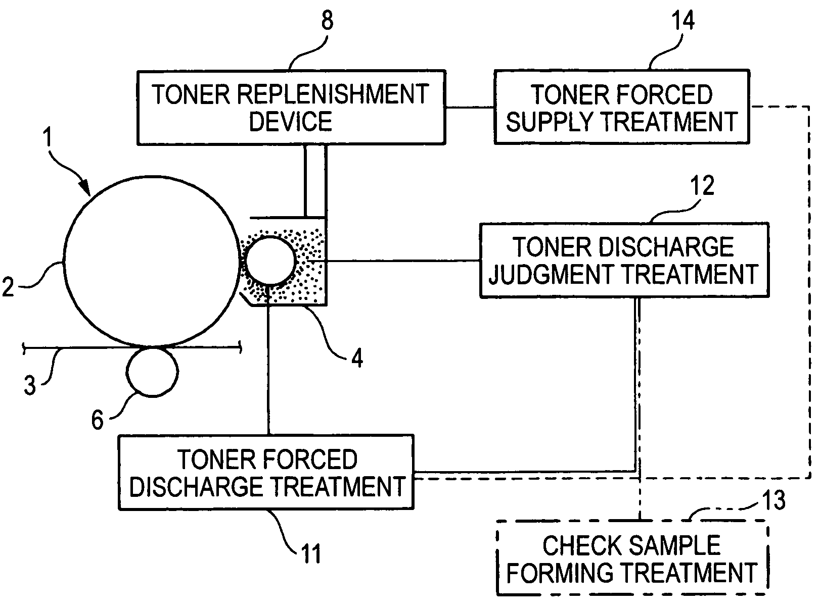
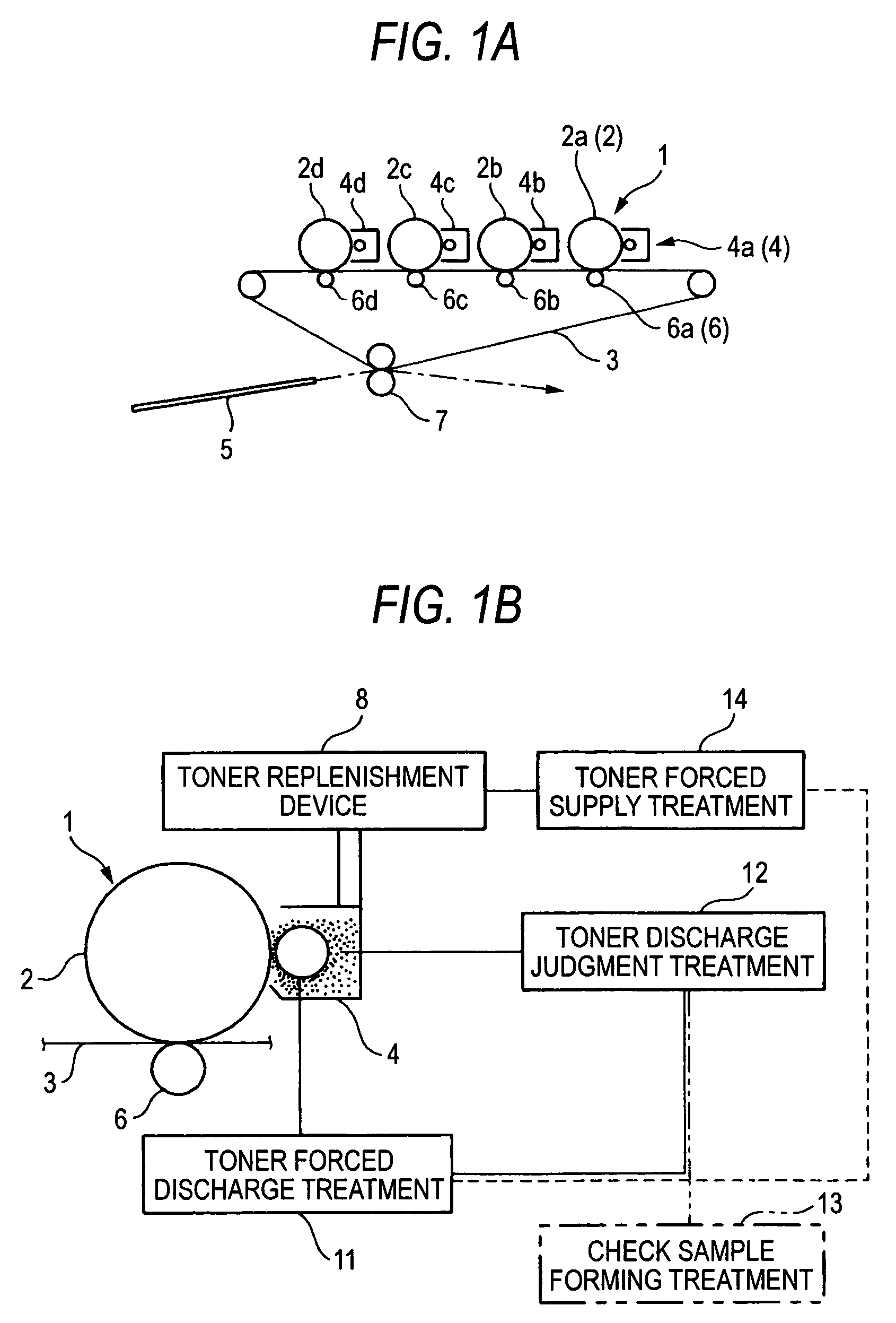
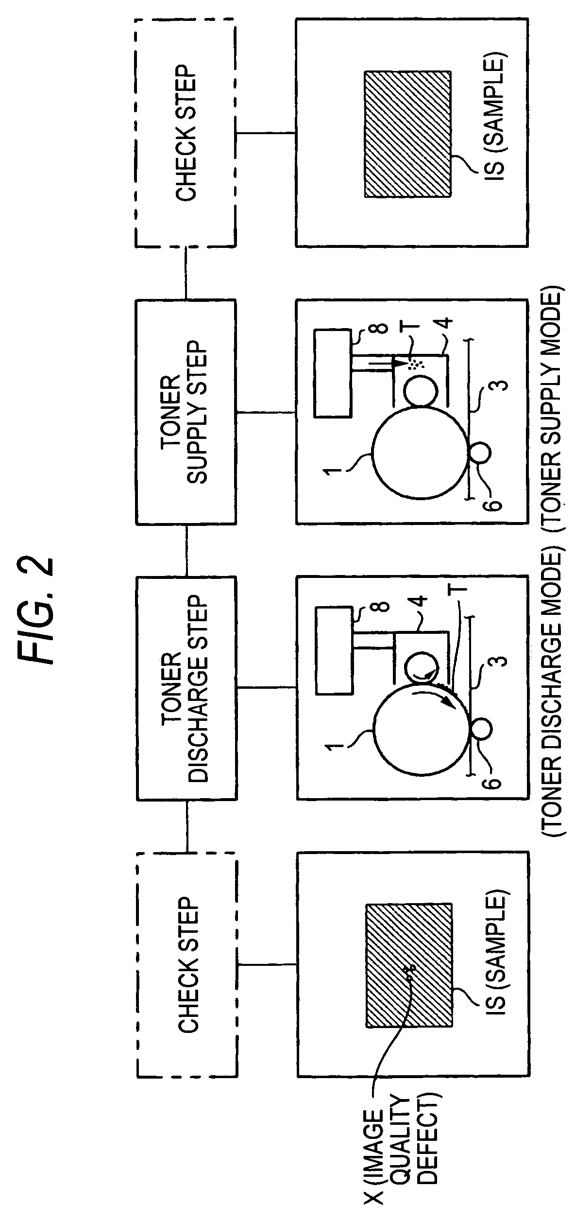
The invention is an image forming apparatus and treatment that can address image quality defects such as white spot defects. The apparatus includes a mechanism for executing a toner discharge mode to force consumed toner from the developing device and deliver it to the image quality defect. The apparatus can also include a toner replenishment device to supply new toner to the developing device in addition to the toner discharge mode. The treatment effectively solves image quality defects and prevents a reduction in image quality due to shortage of toner density.

Problems solved by technology

When the toner agglomerated substances are accumulated inside the developing device and are delivered on an image at the time of outputting a subsequent image of a high image density, there is fear that a region corresponding to the toner agglomerates results in a white spot defect.
Therefore, when an image quality defect such as a white spot defect occurs with respect to quality of an image outputted actually, measures of preventing this defect at once cannot be taken and also in the toner consumption treatment using the inter-image region, an image forming area is small originally, so that it is difficult to sufficiently ensure the amount of consumption of toner and a toner agglomerated substance inside a developing agent tends to be discharged insufficiently.
Particularly in the case of considering a limit of cleaning by a cleaner, an image density of discharge by the toner discharge patch cannot be increased unnecessarily and it becomes more difficult to ensure the amount of consumption of toner.

Method used


Image

  • Image forming apparatus and treatment thereof
  • Image forming apparatus and treatment thereof
  • Image forming apparatus and treatment thereof

Examples


first embodiment

[0095]FIG. 3 is an explanatory diagram showing the whole configuration of a first embodiment of an image forming apparatus to which the invention is applied.

[0096]In FIG. 3, a basic configuration of the image forming apparatus is a configuration constructed so that an image reading unit 21 is disposed in an upper portion of an apparatus body 20 and also an image forming engine 22 equipped with, for example, tandem type image forming units 30 is disposed inside the apparatus body 20 and also sheet supply trays 23, 24 are disposed in a lower portion of this image forming engine 22 and a sheet (paper) supplied from the sheet supply trays 23, 24 is fed to the image forming engine 22 through a sheet transport path 25 and an image is formed on the sheet by this image forming engine 22 and thereafter the sheet on which the image is formed is delivered to the outside of the apparatus body 20 through the sheet transport path 25.

[0097]In the present embodiment, the image forming engine 22 has...

second embodiment

[0162]FIG. 21 shows a second embodiment of an image forming apparatus to which the invention is applied.

[0163]In FIG. 21, a basic configuration of the image forming apparatus is substantially similar to that of the first embodiment, but is designed to perform necessity determination processing of a refresh mode different from that of the first embodiment. Incidentally, detailed description of components similar to those of the first embodiment will be omitted herein by attaching numerals similar to those of the first embodiment.

[0164]In the present embodiment, in the necessity determination processing of a refresh mode, as shown in FIGS. 21 and 22, after producing a check chart by pressing and operating a check chart print switch 81 of a control panel 80, a refresh mode check switch 84 is pressed and operated and thereby, the check chart is read by an image reading unit 21 and a refresh mode for each color component is checked by read information about this check chart and when ther...

third embodiment

[0167]FIG. 24 is an explanatory diagram showing a main part of refresh mode control processing used in a third embodiment of an image forming apparatus according to the invention.

[0168]In FIG. 24, a basic configuration of the image forming apparatus is substantially similar to that of the second embodiment, but unlike the second embodiment, it is constructed so that a check chart is not produced and a necessity determination of a refresh mode is made without using this check chart. Incidentally, in FIG. 24, processing steps similar to the first embodiment are similar to those of the first embodiment.

[0169]That is, in the present embodiment, in the refresh mode necessity determination processing, as shown in FIG. 25, when a refresh mode check switch 84 is pressed and operated, a refresh mode for each color component is checked by the past image output conditions and when there is a color requiring the refresh mode, the refresh mode of the corresponding color is executed and when ther...


PUM


Abstract

An image forming apparatus includes a toner forced discharge treatment for executing a toner discharge mode in which toner inside a developing device is forcedly consumed, and a toner discharge judgment treatment capable of judging necessity of execution of the toner discharge mode based on a decision as to whether or not a toner state inside the developing device is in a state of leading to an image quality defect. Further, the apparatus includes a toner forced supply treatment for executing a toner supply mode in which new toner is supplied from a toner replenishment device to the developing device in addition to execution of the toner discharge mode.

Description

BACKGROUND OF THE INVENTION[0001]1. Field of the Invention[0002]The present invention relates to an image forming apparatus such as a copying machine or a printer, and particularly to improvements in an image forming apparatus and treatment useful in a form of outputting an image forming job in which various images are mixed at high speed.[0003]2. Description of the Related Art[0004]In recent years, in an image forming apparatus using an electrophotographic treatment, more speedup of a print output has advanced while image quality is becoming higher. Particularly in an on-demand print system, each component (particularly, a developing device) of the image forming apparatus is forced to be in an image forming state always in order to output an image forming job in which various images such as a full color image or a monochrome image (for example, a monochrome K image: a monochrome black image) are mixed at high speed.[0005]Under such circumstances, when a developing device continues ...

Claims


Application Information

Patent Timeline
Patent Type & Authority Patents(United States)
IPC IPC(8): G03G15/08
CPCG03G15/553G03G15/556
Inventor TANAKA, SHUJIYUKUTAKE, TAKASHI
Owner FUJIFILM BUSINESS INNOVATION CORP
Learn More