
Optical position sensing device including interlaced groups of photosensitive elements

a technology of optical positioning and photosensitive elements, which is applied in the direction of static indicating devices, counting objects on conveyors, instruments, etc., can solve the problems of limiting the useful life of the device, prone to inaccuracy and malfunction, and complex design. , to achieve the effect of reducing the cost of image processing, and improving the accuracy of image processing

Active Publication Date: 2007-09-11
CYPRESS SEMICON CORP
View PDF78 Cites 25 Cited by
  • Summary
  • Abstract
  • Description
  • Claims
  • Application Information

AI Technical Summary

Problems solved by technology

One problem with mechanical mice is that they are prone to inaccuracy and malfunction after sustained use due to dirt accumulation, and such.
In addition, the movement and resultant wear of the mechanical elements, particularly the shaft encoders, necessarily limit the useful life of the device.
This technology typically provides high accuracy but suffers from a complex design and relatively high image processing requirements.
In addition, the optical efficiency is low due to the grazing incidence of the illumination.
Although a significant improvement over the conventional LED-based optical mice, these speckle-based devices have not been wholly satisfactory for a number of reasons.
In particular, mice using laser speckle have not demonstrated the accuracy typically demanded in state-of-the-art mice today, which generally are desired to have a path error of less than 0.5% or thereabout.

Method used


Image

  • Optical position sensing device including interlaced groups of photosensitive elements
  • Optical position sensing device including interlaced groups of photosensitive elements
  • Optical position sensing device including interlaced groups of photosensitive elements

Examples


Embodiment Construction

Problems with Prior Optical Positioning Devices

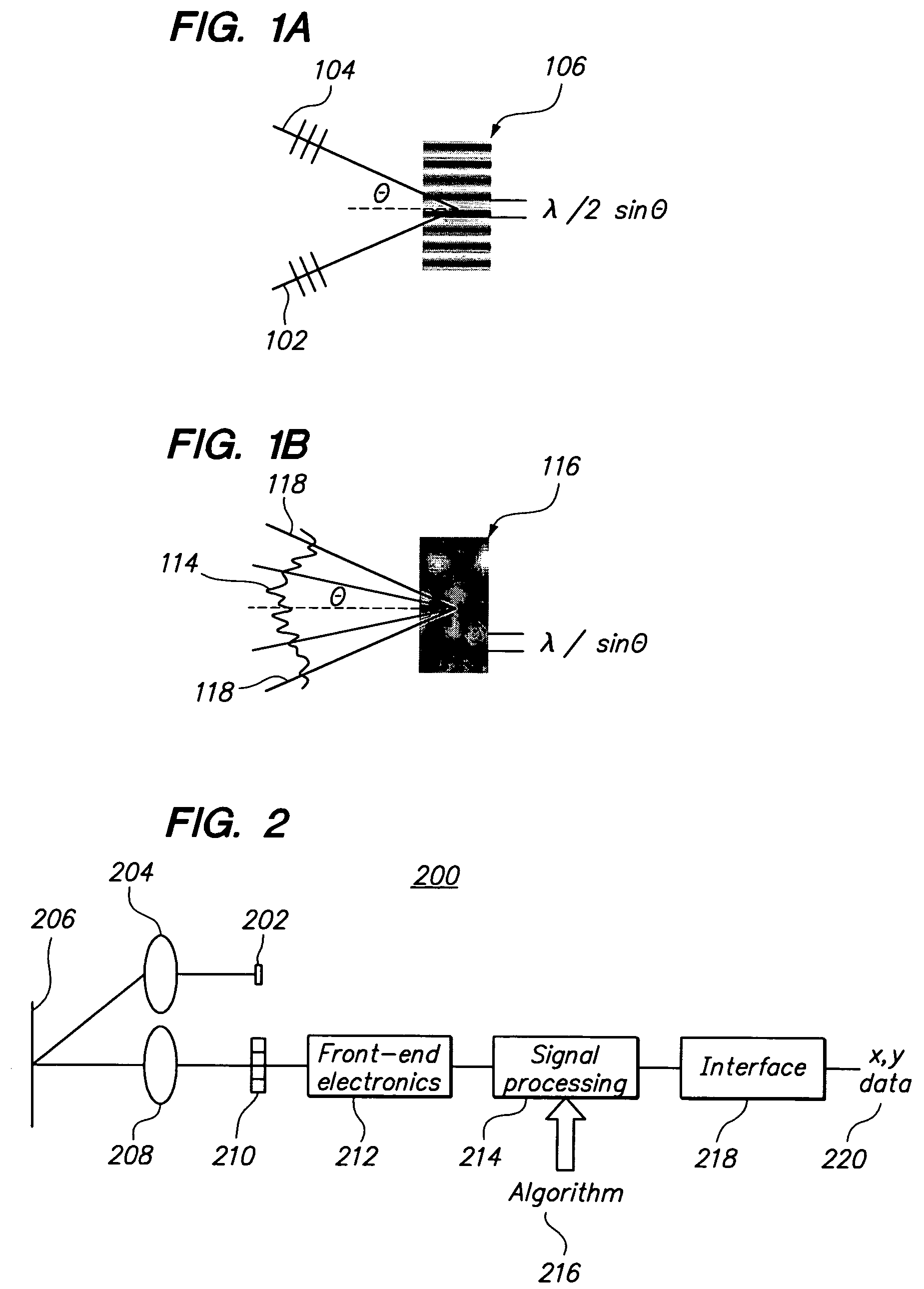
[0037]One problem with prior speckle-based OPDs stems from the pitch or distance between neighboring photodiodes, which typically ranges from ten (10) micrometers to five hundred (500) micrometers. Speckles in the imaging plane having a size smaller than this pitch are not properly detected, thereby limiting the sensitivity and accuracy of the OPD. Speckles significantly larger than this pitch produce a drastically smaller signal.

[0038]Another problem is the coherent light source must be correctly aligned with the detector in order to produce a speckled surface image. With prior designs, the illuminated portion of an image plane is typically much wider than the field of view of the detector to make sure the photodiode array(s) is (are) fully covered by the reflected illumination. However, having a large illuminated area reduces the power intensity of the reflected illumination that the photodiodes can detect. Thus, attempts to solve or ...


PUM


Abstract

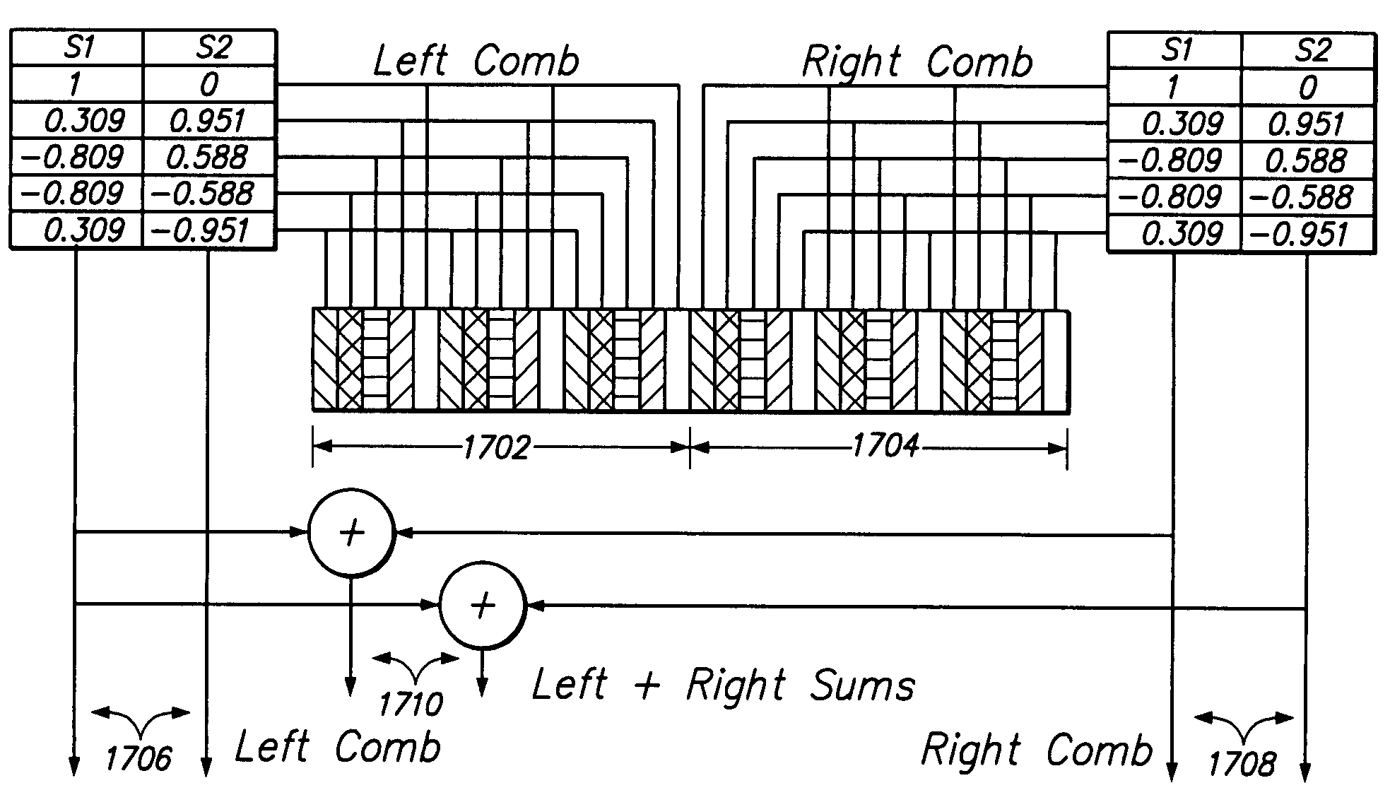
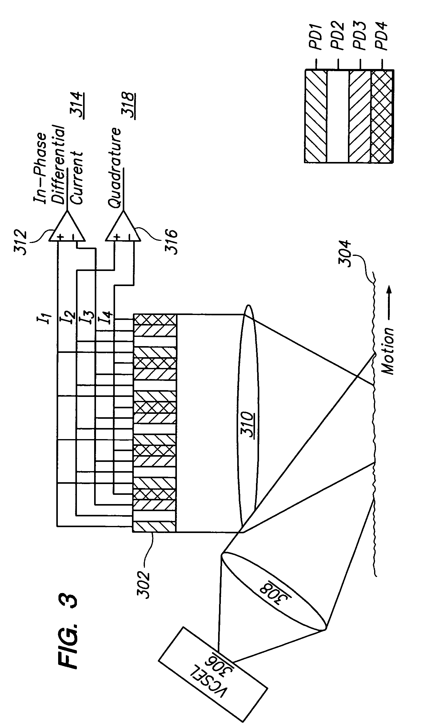
One embodiment described relates to an optical displacement sensor for sensing movement of a data input device across a surface by detecting displacement of optical features in a succession of images of the surface. The sensor includes a detector having an array including a number (N) of sets of photosensitive elements, each set having a number (M) of photosensitive elements, where M is greater than two and not equal to four. Signals from each of the photosensitive elements in a set are electrically coupled or combined with corresponding photosensitive elements in other sets to produce a total of M independent group signals from M interlaced groups of photosensitive elements. Other embodiments are also described.

Description

CROSS-REFERENCE TO RELATED APPLICATIONS[0001]The present application claims the benefit of U.S. provisional application No. 60 / 573,303, entitled “Optical position sensing device having a detector including interlaced groups of photosensitive elements,” filed May 21, 2004, by inventors David A. LeHoty, Charles B. Roxlo, Jahja I. Trisnadi and Clinton B. Carlisle. The disclosure of the aforementioned U.S. provisional application is hereby incorporated by reference in its entirety.TECHNICAL FIELD[0002]The present invention relates generally to an Optical Positioning Device (OPD), and methods of sensing movement using the same.BACKGROUND OF THE INVENTION[0003]Pointing devices, such as computer mice or trackballs, are utilized for inputting data into and interfacing with personal computers and workstations. Such devices allow rapid relocation of a cursor on a monitor, and are useful in many text, database and graphical programs. A user controls the cursor, for example, by moving the mouse...

Claims


Application Information

Patent Timeline
Patent Type & Authority Patents(United States)
IPC IPC(8): G09G5/08G01B11/00G01D5/347G06F3/03H01J40/14
CPCG01B11/002G01D5/34715G06F3/0317
Inventor LEHOTY, DAVID A.ROXLO, CHARLES B.TRISNADI, JAHJA I.CARLISLE, CLINTON B.
Owner CYPRESS SEMICON CORP
Learn More