
Planar electric precipitator

a technology of electric precipitator and electric precipitator, which is applied in the direction of electrostatic separation, solid separation, chemistry apparatus and processes, etc., can solve the problems of inconvenient use, inconvenient manufacture, and difficulty in precisely controlling distances during manufacture, so as to prevent accidental touching, maintain precision, and facilitate manufacture

Inactive Publication Date: 2007-09-11
IND TECH RES INST
View PDF12 Cites 20 Cited by
  • Summary
  • Abstract
  • Description
  • Claims
  • Application Information

AI Technical Summary

Benefits of technology

The present invention is a plane type electric precipitator with a flat shape that can be easily placed on walls, ceilings, or floors without taking up space. It consists of a discharging plate, a collecting plate, and electrode units placed on the electrode plate. The electrodes have electrode tips, and the collecting plate has collectors at positions that correspond to the electrode units. The direct electric voltage applied between the electrodes causes air-cleaning by ionizing suspended particles and trapping them at the collecting plate. The cover plate prevents accidental touching and provides a decorative look. The flat shape and easy manufacturing process make the present invention highly efficient in air-cleaning.

Problems solved by technology

However, conventional electrostatic air cleaning apparatuses generally have large volumes and need to be placed on floors, which consumes valuable space and is inconvenient.
Another shortcoming of conventional electrostatic air cleaning apparatuses is the difficulty during manufacture of precisely controlling distances and mutual orientations between electrodes and collecting plates, so as to prevent smoke from entering air channels and preserving ionizing capability.
The present inventor has been aware that conventional art does not solve the problems of large volume, difficulty of manufacturing and cost reduction.
US005925170A “Electric dust-collection unit and air-cleaning apparatus” discloses an electrostatic air cleaning apparatus having a plurality of electrodes, each made of a wire with a needle tip, oriented parallel to each other, which results in a large thickness and hence a large volume of the apparatus.
Furthermore, the electrodes, being separable from a base, during manufacture need to be placed precisely one by one, which is difficult and expensive.
Therefore, the apparatus has a height that is hard to reduce, resulting in a large volume.
This apparatus has a somewhat reduced thickness, but a satisfactorily small volume is not achieved.
Furthermore, manufacturing by punching and bending into precise angles is difficult due to the elasticity of metal plates, so that precision and hence effectivity of the apparatus are not sufficiently high.

Method used


Image

  • Planar electric precipitator
  • Planar electric precipitator
  • Planar electric precipitator

Examples


first embodiment

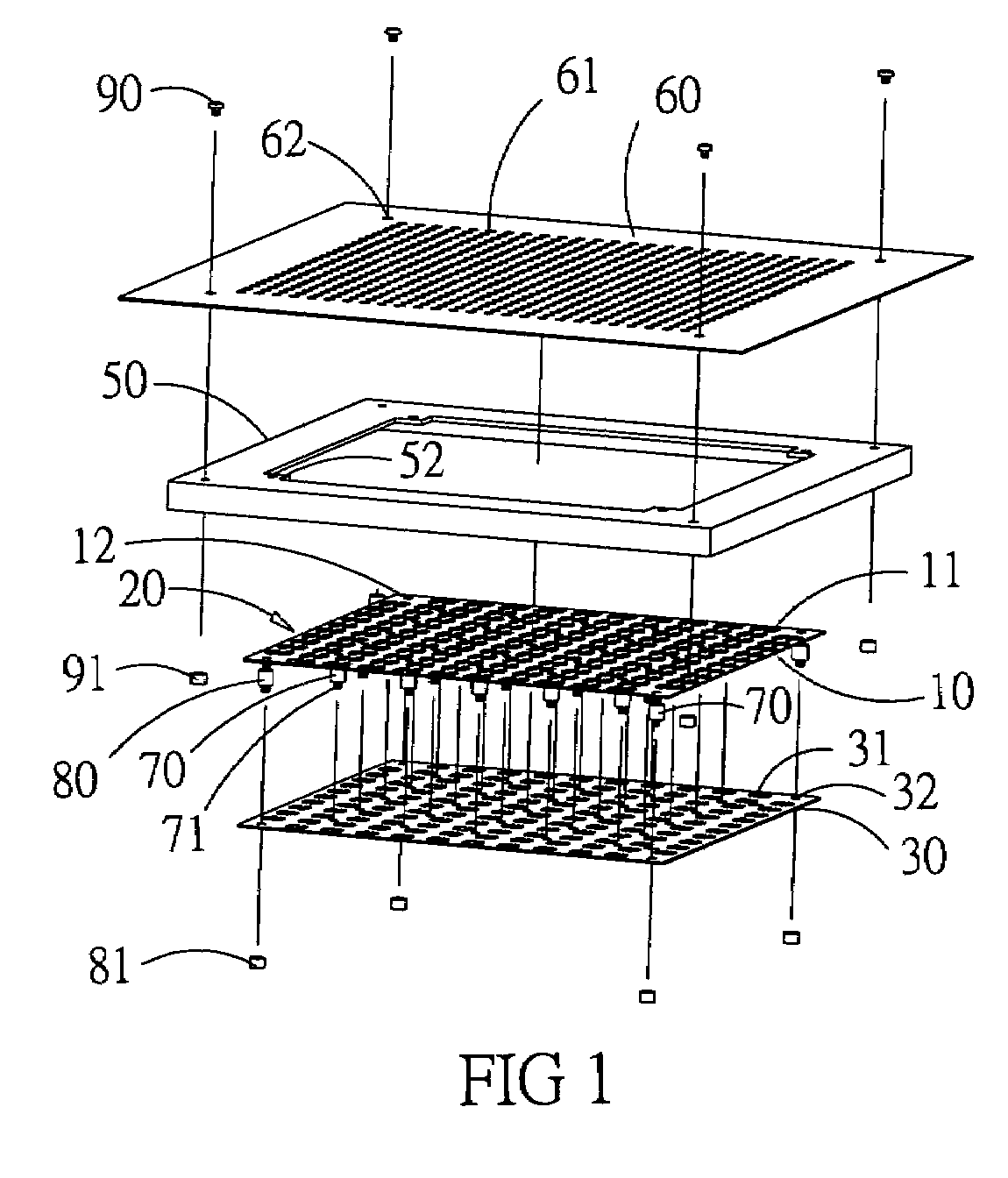
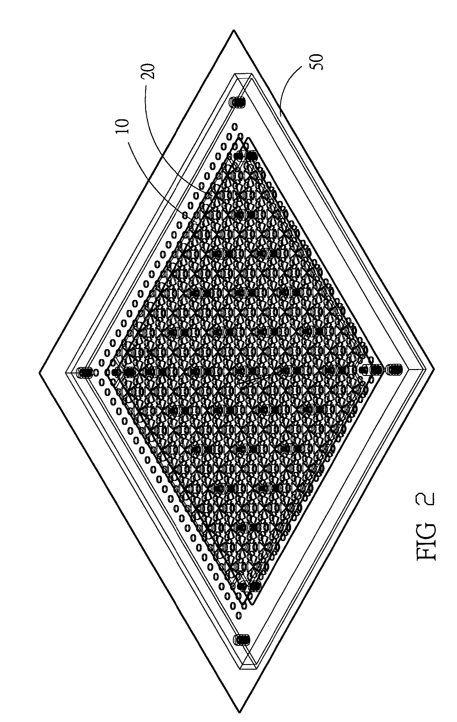
[0029]In the present invention, the electrodes 22 are oriented parallel to the electrode plate 10 and are made by punching or laser cutting, delineating circumferences of the electrode openings 21 and the electrodes 22, so that manufacturing is simple and precision is easily controlled. For the electrode units 20 and the electrode plate 10, readily available parts are used, so that no complicated assembly process is required and cost is reduced.

[0030]Referring to FIGS. 1, 2 and 6, the collecting plate 30 is mounted below the electrode plate 10., with the collecting units 40 and the electrode units 20 facing each other. As shown in FIGS. 5 and 6, each of the collecting units 40 has a collector surface 41, which is formed as a round depression surrounded by several air holes 42. The collectors surfaces 41 are made by punching, and the air holes 42 are made by punching or laser cutting, resulting in a simple manufacturing process.

[0031]Referring again to FIG. 6, the electrode units 20 ...

second embodiment

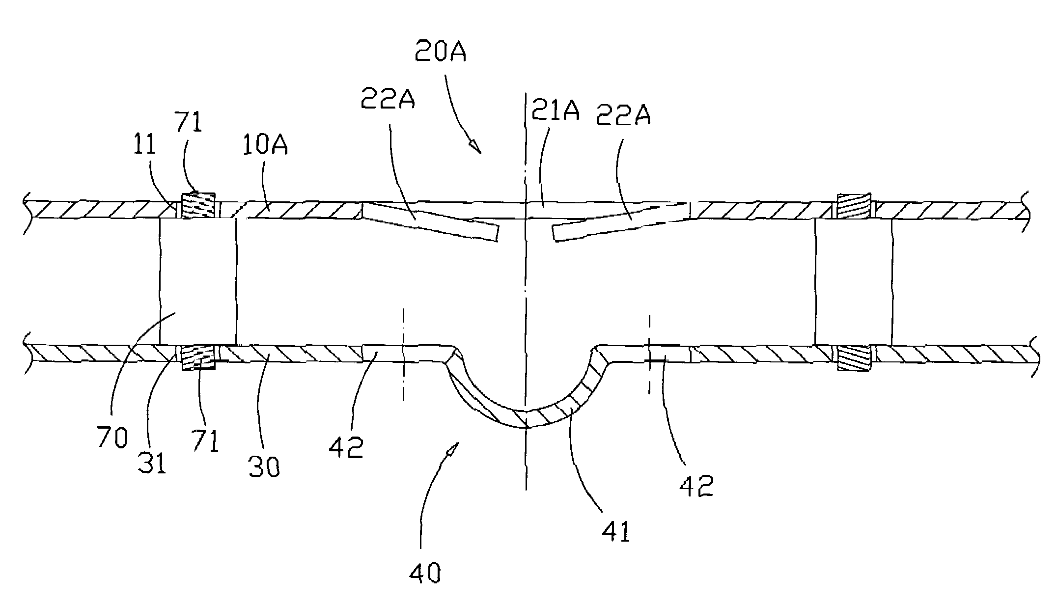
[0043]Referring to FIGS. 7-8, the present invention in a second embodiment has electrode units 20A with electrodes tips 22A that are bent towards the collecting plate 30 at defined angles, having tips that are closer to the collecting plate 30 than the distance between the electrode plate 10 to the collecting plate 30.

third embodiment

[0044]Referring to FIG. 9, the present invention in a third embodiment has a collecting plate 30A which is a single plane sheet without a collecting unit, with electric discharge occuring between the electrodes 22 of the electrode units 20 and the collecting plate 30A.


PUM


Abstract

A plane type electric precipitator includes an electrode plate of plane shape, made of electricity-conducting material; a collecting plate, parallel to the electrode plate and made of electricity-conducting material; a plurality of electrode units, placed on the electrode plate and having tips; wherein direct electric voltage is applied between the electrode plate and the collecting plate, so that air passing through is exposed to high electric fields close to the tips of the electrode units, ionizing suspended particles and trapping ionized particles at the collecting plate, so that an air-cleaning effect results.

Description

BACKGROUND OF THE INVENTION[0001]1. Field of the Invention[0002]The present invention relates to a planar electric precipitator, particularly to a planar electric precipitator which is easy to manufacture and of flat shape to be suitable for industrial and home use.[0003]2. Description of Related Art[0004]In conventional art, particles suspended in the air are removed by letting an air flow pass through a channel in which a pointed electrode is placed. Direct voltage between the electrode and a collecting plate causes the particles contained in the air flow to be ionized and drawn towards the collecting plate and thus to be removed from the air.[0005]Electrostatic air cleaning apparatuses as just described work effectively and therefore are widely used to clean air in closed rooms. However, conventional electrostatic air cleaning apparatuses generally have large volumes and need to be placed on floors, which consumes valuable space and is inconvenient.[0006]The main reason for a lar...

Claims


Application Information

Patent Timeline
Patent Type & Authority Patents(United States)
IPC IPC(8): B03C3/12B03C3/40
CPCB03C3/09B03C3/12
Inventor CHANG, KAI-CHENGCHANG, CHIA-YUAN
Owner IND TECH RES INST
Learn More