
Rock drilling rig and rock breaking machine

Inactive Publication Date: 2007-09-11
SANDVIK TAMROCK
View PDF10 Cites 16 Cited by
  • Summary
  • Abstract
  • Description
  • Claims
  • Application Information

AI Technical Summary

Benefits of technology

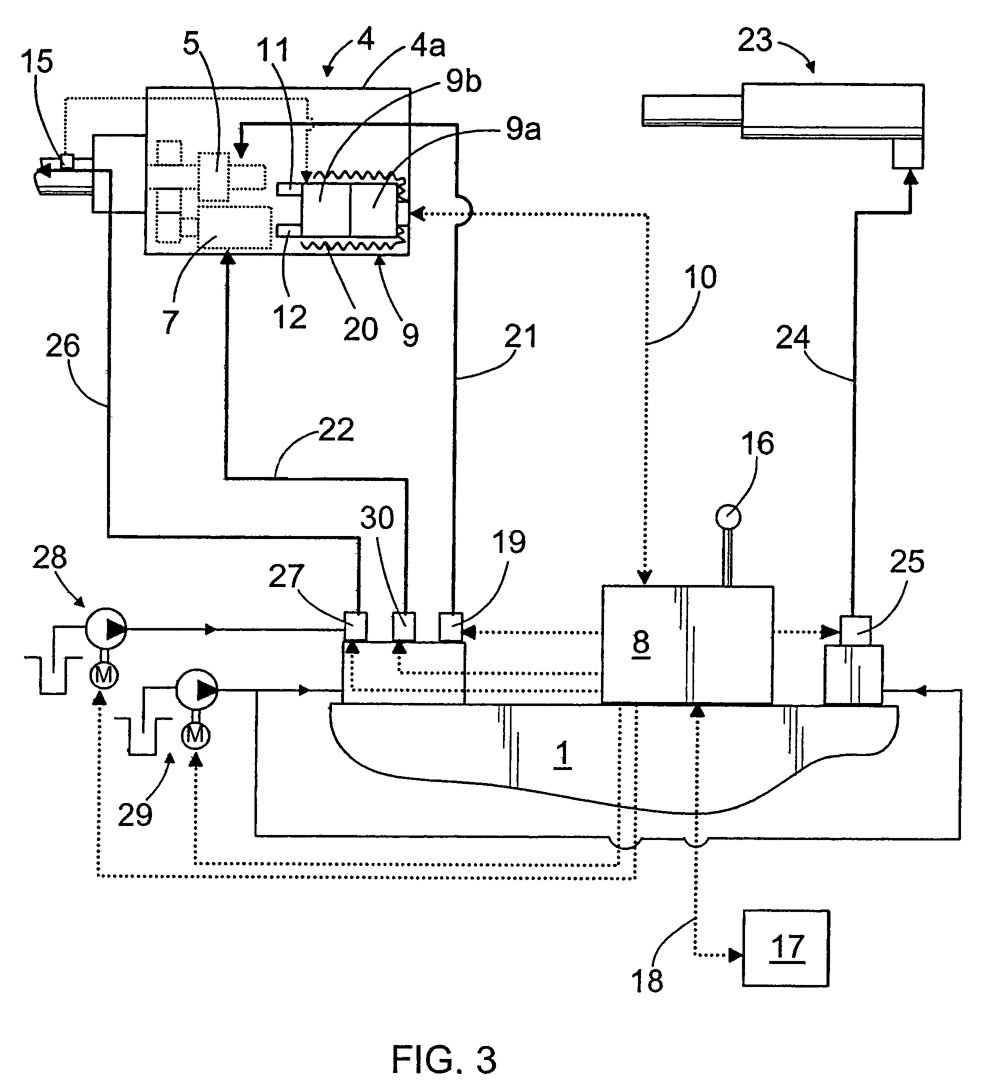
[0008]The essential idea of the invention is that for controlling drilling, a first control unit is arranged on the carrier of the rock drilling rig and a second control unit is arranged to the rock drilling apparatus. Said control units communicate with each other using a data communications link arranged between them. One or more sensors are arranged to the drilling apparatus to monitor the operation of the drilling apparatus during drilling. Measuring results received from the sensors are transmitted to the second control unit that comprises a memory unit and processing unit. The basic settings of the drilling apparatus can be stored in the memory unit. The processing unit is in turn arranged to calculate parameters describing the operating state of the drilling apparatus on the basis of the measuring information received from the sensors and the basic settings stored in the memory unit. From the second control unit, the parameters are transmitted to the first control unit arranged on the carrier of the drilling rig that controls the actuators affecting the operation of the drilling apparatus, such as valves or electric regulating elements, on the basis of the parameters and control commands given to the second control unit so as to achieve the desired operating state of the drilling apparatus. Because the prevailing operating state of the drilling apparatus is defined already in the drilling apparatus, the control unit arranged on the carrier can be a relatively simple one. At its simplest, the first control unit is a control element, by means of which the desired drilling values are entered into the control system. Because the equipment for defining the operating state of an individual drilling apparatus, i.e. the sensors and second control unit, is arranged to the drilling apparatus, the replacement of the entire drilling apparatus or a later modification of the original drilling apparatus is simple and does not cause difficult changes to the control system in the rock drilling rig.
[0009]The essential idea of an embodiment of the invention is that the second control unit is arranged inside the rock drilling apparatus where it is protected from dents and ambient conditions. In addition, at least some of the sensors are integrated as part of the control unit so that the control unit and sensors form together a compact entity. Even weak measuring signal received from the sensors can then be received by the second control unit. All in all, the measuring results can thus be made more accurate, which enables an accurate control of the drilling apparatus. Further, this type of control unit is easy to replace, if the control of the drilling apparatus later requires updating.
[0010]The essential idea of an embodiment of the invention is that between the first and second control units, there is a CAN (Controller Area Network) bus that also enables a versatile monitoring of the drilling apparatus. Through monitoring, detected and starting defects can efficiently be communicated to the user. The CAN bus has proven a reliable solution in demanding conditions.
[0011]The essential idea of an embodiment of the invention is that the second control unit comprises an identifier that the first control unit is arranged to read automatically, whereby the drilling apparatus connected to the rock drilling rig is always explicitly identified. This facilitates the possible replacement of the drilling apparatus.

Problems solved by technology

A drawback of the known rock drilling rigs is that the control unit is far away from the rock drilling apparatus.
This means that the relatively weak measuring signal received from the sensors arranged in the drilling apparatus is easily disturbed, which reduces measuring accuracy.

Method used


Image

  • Rock drilling rig and rock breaking machine
  • Rock drilling rig and rock breaking machine
  • Rock drilling rig and rock breaking machine

Examples


Embodiment Construction

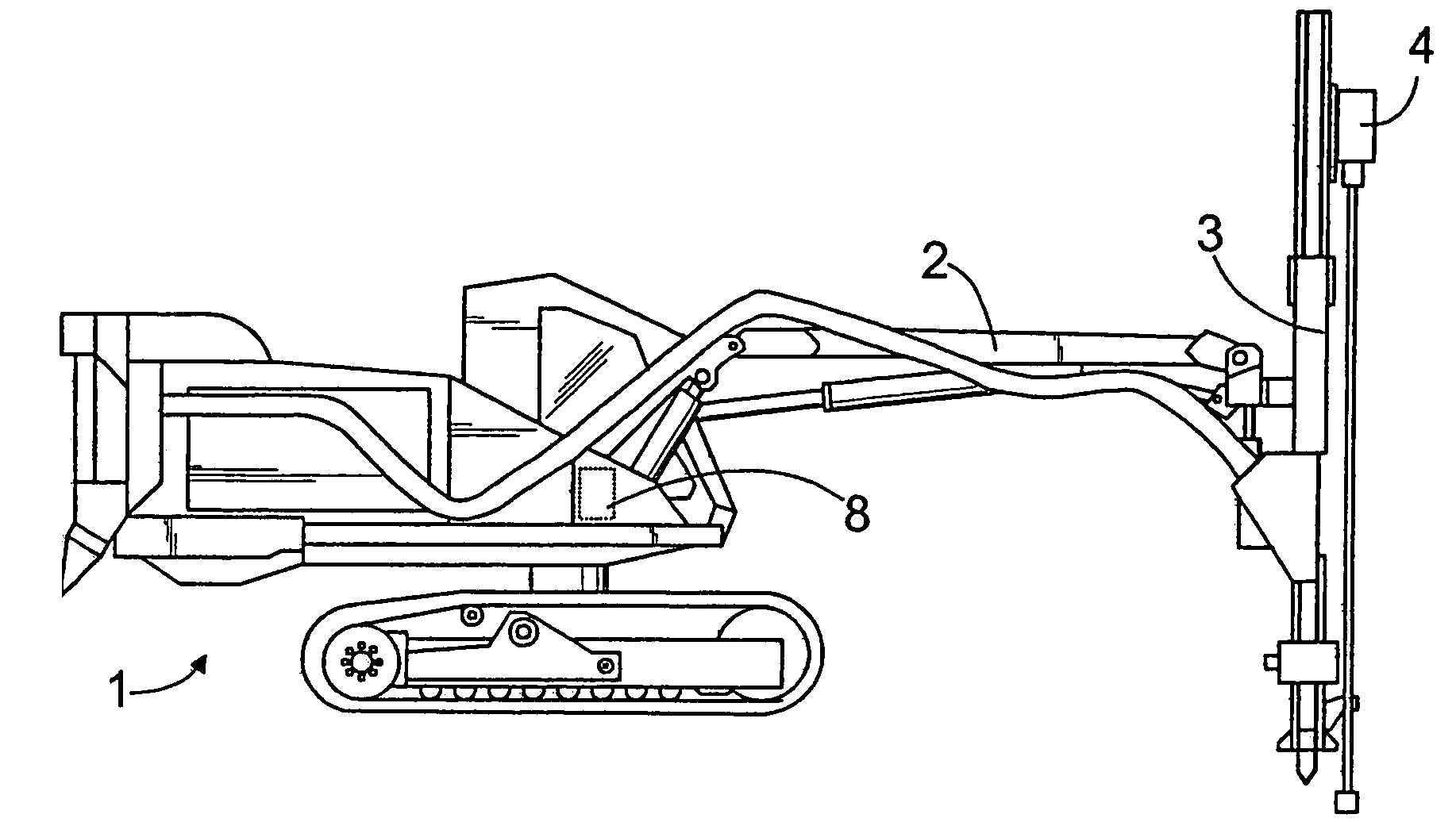
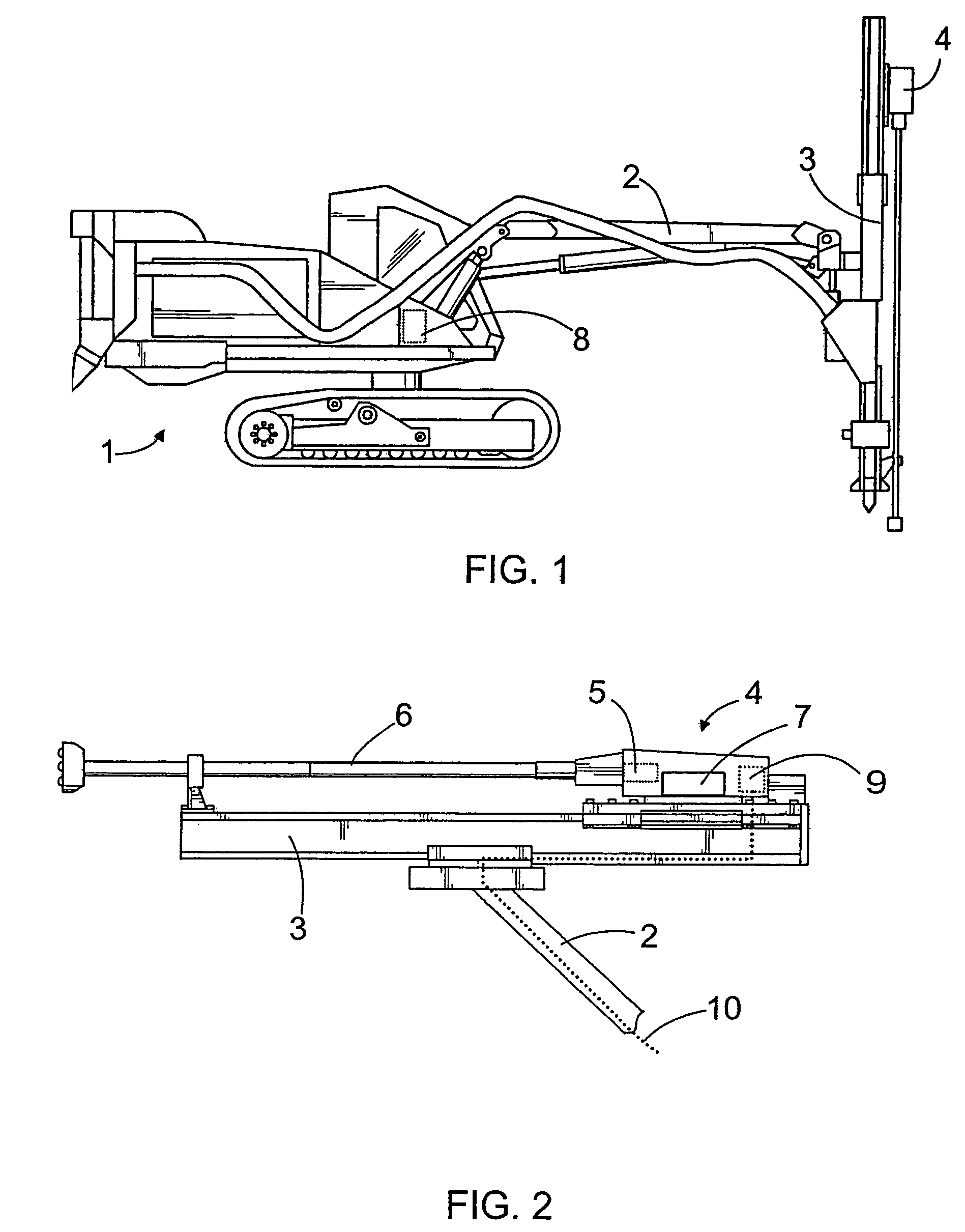
[0017]The rock drilling rig shown in FIG. 1 comprises a movable carrier 1, a boom 2 arranged movable in relation to the carrier, and a feeding beam 3 arranged to the free end of the boom. In some cases, the feeding beam 3 can be arranged directly on the carrier 1. A rock drilling apparatus 4 can be moved in relation to the feeding beam 3 by means of suitable actuators.

[0018]FIG. 2 shows a rock drilling apparatus 4 comprising a percussion device 5 for providing impact pulses to a tool 6 connected to the drilling apparatus. Further, the rock drilling apparatus usually comprises a rotating device 7 for rotating the tool 6 around its longitudinal axis. Because the general structure and operation of a rock drilling rig and rock drilling apparatus are obvious to a person skilled in the art, they need not be described in more detail in this application.

[0019]FIG. 3 shows the principle of a control system of the invention. The control system comprises a first control unit 8 arranged on the ...


PUM


Abstract

The rock drilling rig comprises a first control unit (8) arranged on a carrier (1) and a second control unit (9) arranged to a rock drilling apparatus (4). The first control unit (8) and the second control unit (9) communicate with each other by means of a first data communications link (10). The rock drilling apparatus (4) has one or more sensors (11, 12, 15), the measuring results of which are processed in the second control unit (9) and only then transmitted to the first control unit (8) that controls actuators regulating the operation of the rock drilling apparatus (4). Correspondingly, the rock breaking machine, such as a breaking hammer, comprises one or more sensors (11, 12, 15) and a control unit (9).

Description

CROSS-REFERENCE TO RELATED APPLICATIONS[0001]This application is a continuation of PCT / FI02 / 00812, filed on Oct. 18, 2002.BACKGROUND OF THE INVENTION[0002]The invention relates to a rock drilling rig comprising a carrier, feeding beam, rock drilling apparatus movable in relation to the feeding beam and having a percussion device, one or more sensors arranged to the rock drilling apparatus to monitor the operation of the rock drilling apparatus, and further at least one first control unit arranged on the carrier of the rock drilling rig to control the operation of the rock drilling apparatus on the basis of measuring information received from the sensors.[0003]The invention further relates to a rock breaking machine comprising a body, percussion device arranged inside the body to generate impact pulses to a tool connectable to the rock breaking machine, and one or more sensors arranged to monitor the operation of the apparatus.[0004]In prior art rock drilling rigs, the operation of t...

Claims


Application Information

Patent Timeline
IPC IPC(8): E21B1/00E21B44/00E02F9/20E21B7/02E21B15/04
CPCE02F9/2025E21B7/022E21B7/025E02F9/26
Inventor SAHA, HEIKKI
Owner SANDVIK TAMROCK
Learn More