Flow labels

a flow label and label technology, applied in the field of flow labels, can solve the problems of congestion, data throughput exceeding data throughput, congestion at a node,

Active Publication Date: 2007-09-04
CRYSTAL MOUNTAIN COMM LLC
View PDF9 Cites 25 Cited by
  • Summary
  • Abstract
  • Description
  • Claims
  • Application Information

AI Technical Summary

Benefits of technology

[0044]Embodiments of the present invention also result in a more secure use of the flow label, providing an efficient way of validating the contents of the flow label, and rejecting a data flow if it has been tampered with.
[0045]Furthermore, embodiments of the present invention also make it possible to use a flow label with an IP domain with multiple DiffServ ingress routers (routers that handle data flow into a domain, such as an edge router) without knowing in advance, through which ingress router the flow enters the domain. This is possible, because each ingress router can verify the validity of the flow label marking without prior per-router configuration. An alternative to the scheme would require that a flow-specific filter be configured to each ingress router separately.

Problems solved by technology

Typically, congestion occurs at a node when the node has a lower data throughput rate than the node that precedes it in the same direction or flow.
Similarly, congestion occurs when a node receives data from a plurality of data sources and the sum of the input data rates exceeds the data throughput of the node.
Packet loss generally occurs at the buffers of an IP router.
When cryptographic methods are used, such as IPSec (IP security protocol), higher-layer headers may not be available in plaintext, thereby removing the ability to identify the flow using the higher-layer headers.
However, the use of the 20-bits of the flow label has not yet been standardized, and currently there are no plans to do so.
A problematic area in their use is termed ‘theft-of-service’, which could affect the use of a flow label for QoS.
The result is that the packet data of the data flow may not be processed in the manner allowed to the sender by the network operator.

Method used


Image

  • Flow labels
  • Flow labels
  • Flow labels

Examples


Embodiment Construction

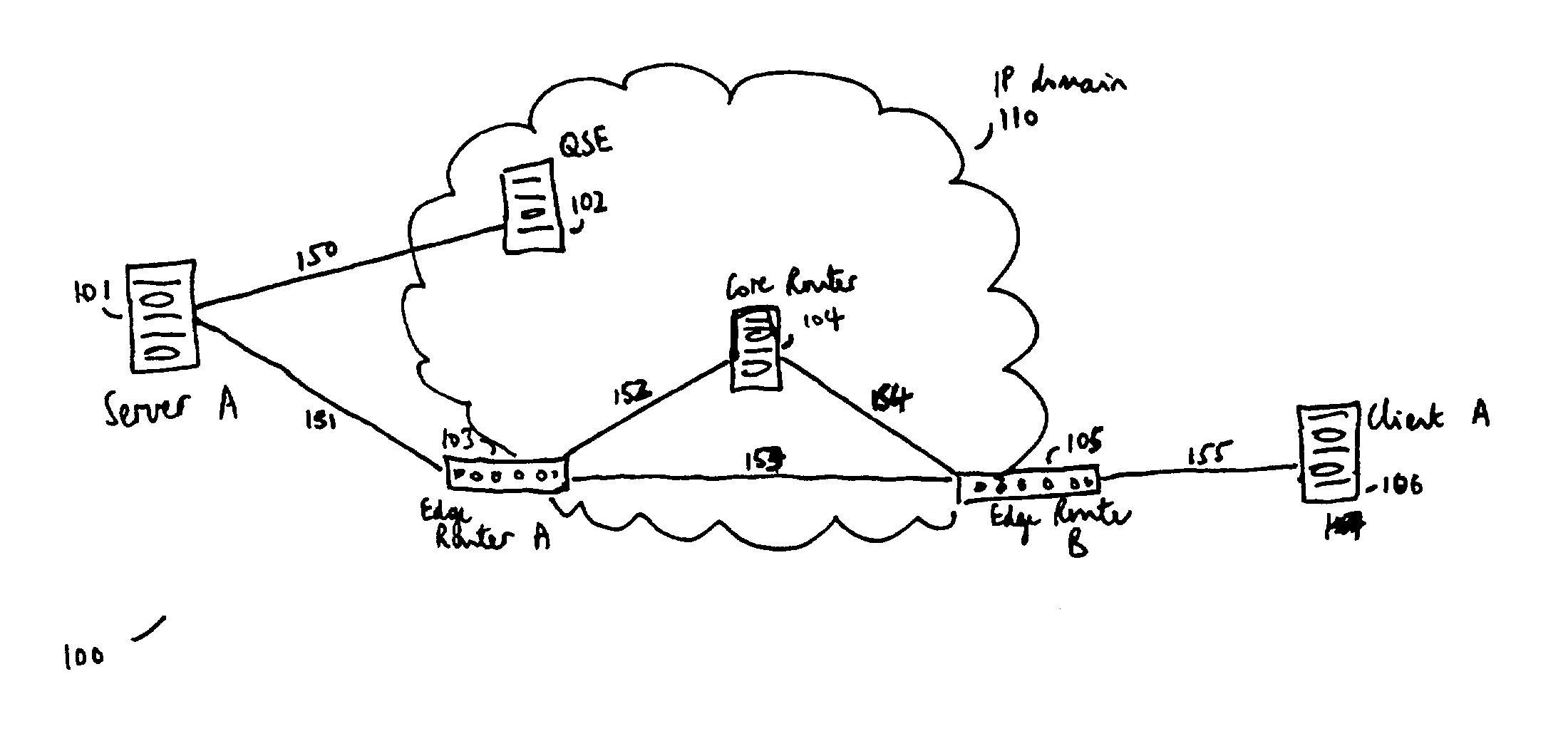
[0052]FIG. 1 shows a communications network 100 of an embodiment of the present invention comprising a server A 101, a QoS signaling entity, QSE, 102, an edge router A 103 and an edge router B 105, a core router 104, and a client A 106. The edge routers, QSE, and core router all belong to the IP routing domain 110. QoS in the IP domain is governed by the QSE. In a preferred embodiment, the QoS in the IP domain is supported using DiffServ, and associated markers such as DSCP.

[0053]The QSE and the server A can communicate with each other via communication link 150. The QSE and the server A can also be connected via the edge router A. The server A and the edge router A can communicate with each other via communication link 151. The edge router A is located at the edge of the IP domain. The edge router A can communicate with the core router and the edge router B via communication links 152 and 153 respectively. Furthermore, the edge router B, which is located at the edge of the IP domai...


PUM


Abstract

There is disclosed a system for monitoring a packet data flow, comprising: a data flow source element including: determining means adapted to determine a quality of service identifier for the data flow; first generating means adapted to generate an encoded value in dependence on the quality of service identifier; allocating means adapted to allocate the quality of service identifier and the encoded value to the flow label for each data packet of the data flow; and transmitting means for forwarding data packets including flow labels to a routing domain; and a routing domain interface element including: receiving means for receiving data packets from the data flow source; second generating means adapted to generate a further encoded value in dependence on the quality of service identifier in a flow label of a data packet; comparing means adapted to compare the further encoded value to the encoded value in the flow label; and routing means adapted to selectively route the data packets in dependence on the comparing step.

Description

FIELD OF INVENTION[0001]The present invention relates to allocating a flow label for a packet data flow.BACKGROUND TO THE INVENTION[0002]Communications networks are commonplace today, providing communication services between users. Some of these networks are adapted to handle packet data, where individual data packets or units are used for transferring the data in the communication between two or more signaling points, such as two terminals or other nodes in the communication system. Packet data networks may be roughly divided into two categories: connection-oriented and connectionless.[0003]In connection-oriented networks, also known as circuit switched networks, a virtual-circuit is set up between the source and destination node using appropriate call set-up and admission control techniques. This circuit, which may span several intermediate nodes in the network, remains open for the duration of the communication, with all data packets relating to the communication being transmitte...

Claims


Application Information

Patent Timeline
Patent Type & Authority Patents(United States)
IPC IPC(8): H04L12/56
CPCH04L45/12H04L45/302H04L45/38H04L47/10H04L47/14H04L47/2408H04L47/32H04L63/1466H04W8/04
Inventor RAISANEN, VILHO I.
Owner CRYSTAL MOUNTAIN COMM LLC
Why Eureka
Try Eureka