
Programmable differential signaling system

a differential signaling and data transmission technology, applied in the field of data communication, can solve the problems of relatively slow data rate, adverse effects on vos and vod, and difficult cmos process

Active Publication Date: 2007-09-04
XILINX INC
View PDF4 Cites 7 Cited by
  • Summary
  • Abstract
  • Description
  • Claims
  • Application Information

AI Technical Summary

Benefits of technology

[0024]In another embodiment, a low voltage differential signal (LVDS) driver includes a first LVDS node, a second LVDS node, a load impedance circuit, and a switching circuit. The load impedance circuit is operably coupled between the first and second LVDS nodes. The switching circuit is operably coupled to provide a differential signal at the first and second LVDS nodes in accordance with an input signal, wherein the switching circuit includes a plurality of current controlled switching transistor circuits.
[0025]I

Problems solved by technology

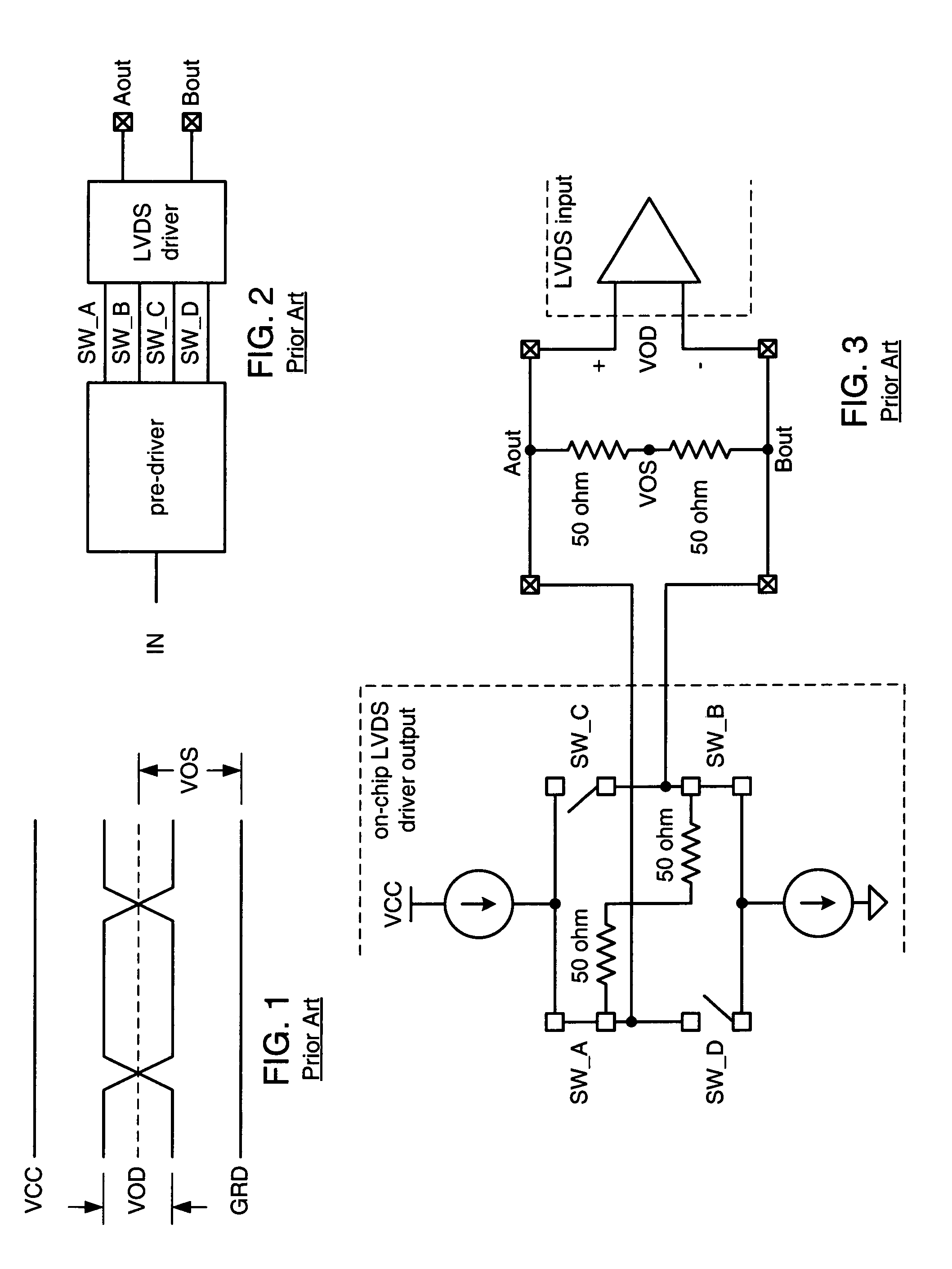
However, it did so at relatively slow data rates (e.g., less than approximately 300 MHz).
Accordingly, to maintain an accurate LVDS signaling, the pull up circuitry needs to substantially match the pull down circuitry, which, in a CMOS process, is extremely difficult.
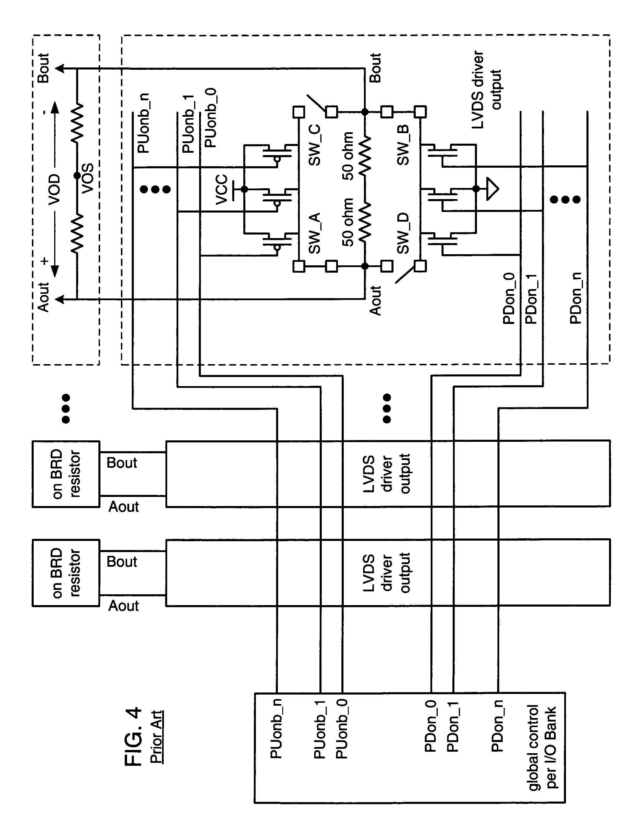
While this is a relatively simple implementation to achieve a single circuit that accommodates multiple signaling conventions, it requires memory space and, if implemented in a CMOS process, the pull up current and pull down currents may differ to the point of failing the specified values of Vos and Vod.
Further, Vos and Vod may be adversely affected by variations and / or noise on VCC and ground.
While this embodiment allows finer tuning of the signal conventions than the embodiments of FIGS. 4 and 5, it still suffers from the adverse affects of a CMOS implementation and variations and / or noise on VCC and ground.
However, the resistance values of the transistors vary considerably more than poly-resistors and makes it difficult to consistently achieve 100 Ohms.

Method used


Image

  • Programmable differential signaling system
  • Programmable differential signaling system
  • Programmable differential signaling system

Examples


Embodiment Construction

[0047]FIG. 10 illustrates an FPGA architecture 200 that includes a large number of different programmable tiles including multi-gigabit transceivers (MGTs 201), configurable logic blocks (CLBs 202), random access memory blocks (BRAMs 203), input / output blocks (IOBs 204), configuration and clocking logic (CONFIG / CLOCKS 205), digital signal processing blocks (DSPs 206), specialized input / output blocks (I / O 207) (e.g., configuration ports and clock ports), and other programmable logic 208 such as digital clock managers, analog-to-digital converters, system monitoring logic, and so forth. Some FPGAs also include dedicated processor blocks (PROC 210).

[0048]In some FPGAs, each programmable tile includes a programmable interconnect element (INT 211) having standardized connections to and from a corresponding interconnect element in each adjacent tile. Therefore, the programmable interconnect elements taken together implement the programmable interconnect structure for the illustrated FPGA....


PUM


Abstract

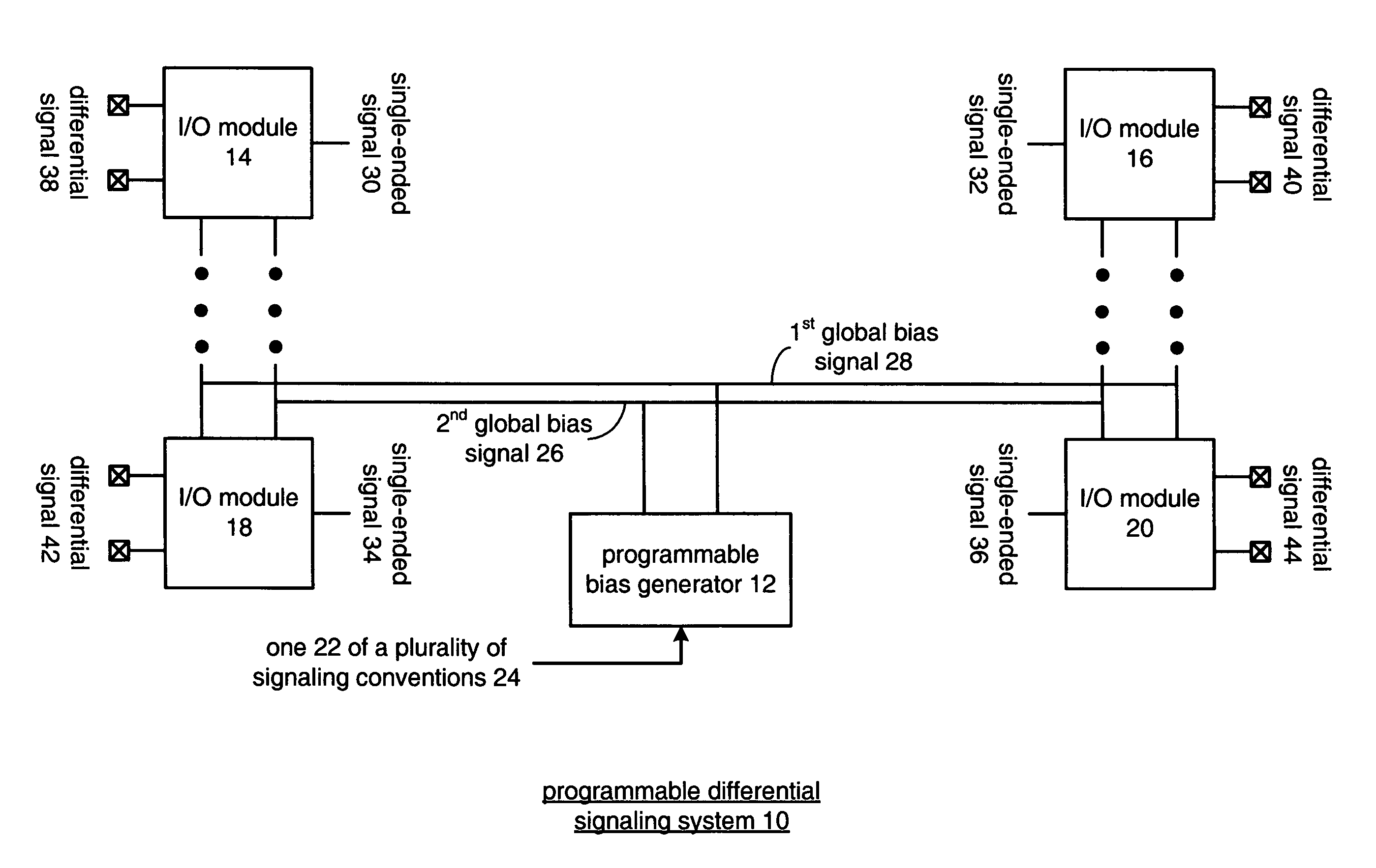
A programmable differential signaling system includes a programmable bias generator and a plurality of input / output modules. The programmable bias generator is operably coupled to generate a first global bias signal and a second global signal based on desired signal properties of one of a plurality of differential signaling conventions. The a plurality of input / output modules is operably coupled to convert between differential signaling and single ended signaling, wherein actual signal properties of the differential signaling are regulated based on the first and second global bias signals to substantially equal the desired signal properties.

Description

BACKGROUND OF THE INVENTION[0001]1. Technical Field of the Invention[0002]This invention relates generally to data communication and more particularly to data transmissions.[0003]2. Description of Related Art[0004]Communication systems are known to transport large amounts of data between a plurality of end user devices, which, for example, include telephones, facsimile machines, computers, television sets, cellular telephones, personal digital assistants, etc. As is also known, such communication systems may be local area networks (LANs) and / or wide area networks (WANs) that are stand-alone communication systems or interconnected to other LANs and / or WANs as part of a public switched telephone network (PSTN), packet switched data network (PSDN), integrated service digital network (ISDN), the Internet, etc. As is further known, communication systems include a plurality of system equipment to facilitate the transporting of data. Such system equipment includes, but is not limited to, r...

Claims


Application Information

Patent Timeline
IPC IPC(8): H03K19/0175
CPCH04L25/0264H04L25/0272H04L25/028H04L25/0288
Inventor ZHOU, SHI-DONGHUANG, GUBONGUYEN, ANDY T.CLINE, RONALD L.
Owner XILINX INC
Learn More