
Battery system with excellent controllability for temperature

a battery system and temperature control technology, applied in the field of battery systems, can solve the problems of insufficient output, difficult temperature elevation, and difficulty in rapid temperature control, and achieve the effects of improving heat conduction efficiency, reducing heat capacity, and improving heat conduction from the external

Inactive Publication Date: 2007-09-04
NISSAN MOTOR CO LTD
View PDF24 Cites 68 Cited by
  • Summary
  • Abstract
  • Description
  • Claims
  • Application Information

AI Technical Summary

Benefits of technology

[0009]The present invention was made in order to solve the foregoing problems. An object of the present invention is to provide a battery system, which is easily subjected to the temperature control, and particularly, can be heated up rapidly at the starting time.
[0012]To the battery system of the present invention, the solid electrolyte is applied, whereby means for liquid-tightly sealing the cell is omitted. The liquid-tightly sealing means is omitted, whereby each cell is miniaturized to decrease the heat capacity, and each cell is formed in the thin plate shape to achieve improvement of heat conduction efficiency. Moreover, the heat mediating structure is inserted between the cells, whereby improvement of the heat conduction from the external temperature controlling means is achieved. By adopting such a configuration, it is made possible to heat or cool the battery system rapidly. Particularly, it is made possible to elevate the temperature of the battery system rapidly at the starting time.

Problems solved by technology

In the case of using the battery in winter or in a cold district, since a battery system is at low temperature at an initial stage of operation, there has been a problem that a sufficient output is not obtained until the temperature is elevated.
However, since the proposed secondary battery has a large heat capacity, there have been problems that temperature elevation thereof is not easy and rapid temperature control therefor is difficult.
Therefore, the proposed secondary battery is inevitably enlarged and will have a large heat capacity.
Hence, even if the external means for heating the battery is introduced, the rapid temperature elevation and temperature control have been difficult.

Method used


Image

  • Battery system with excellent controllability for temperature
  • Battery system with excellent controllability for temperature
  • Battery system with excellent controllability for temperature

Examples


Embodiment Construction

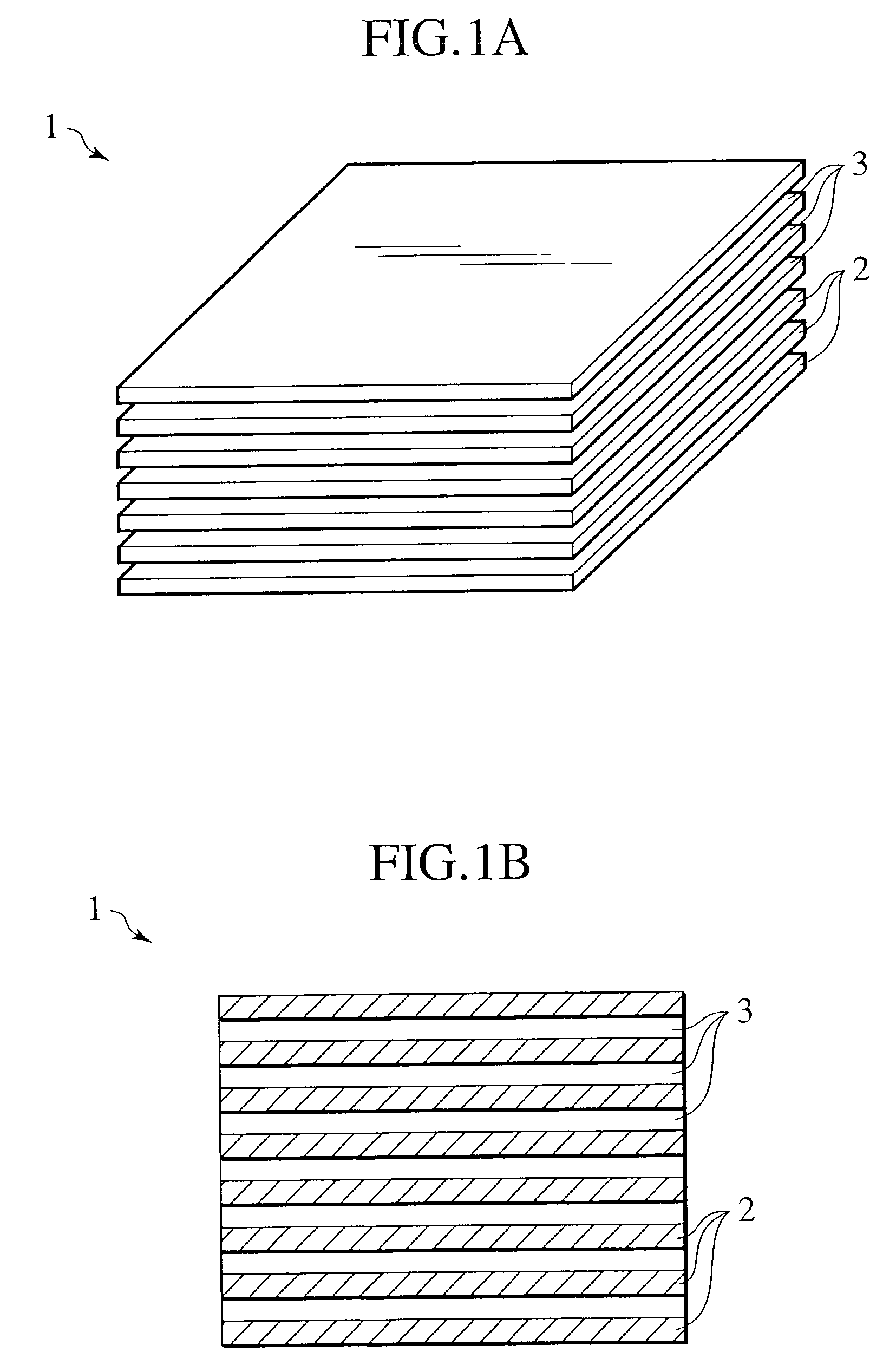
[0026]Description will be made for a battery system according to a first embodiment of the present invention with reference to FIGS. 1A to 2.

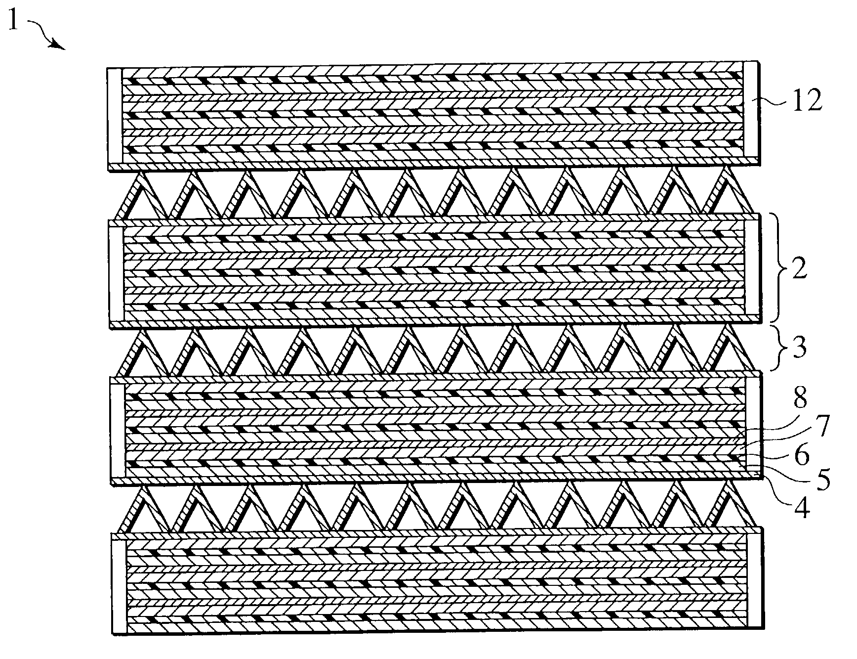
[0027]As shown in FIGS. 1A and 1B, a battery system 1 includes a plurality of cell groups 2 and a plurality of heat mediating structures 3, which are alternately stacked. Each of the cell groups 2 is formed in a thin plate shape, and heated and cooled effectively by the heat mediating structures 3.

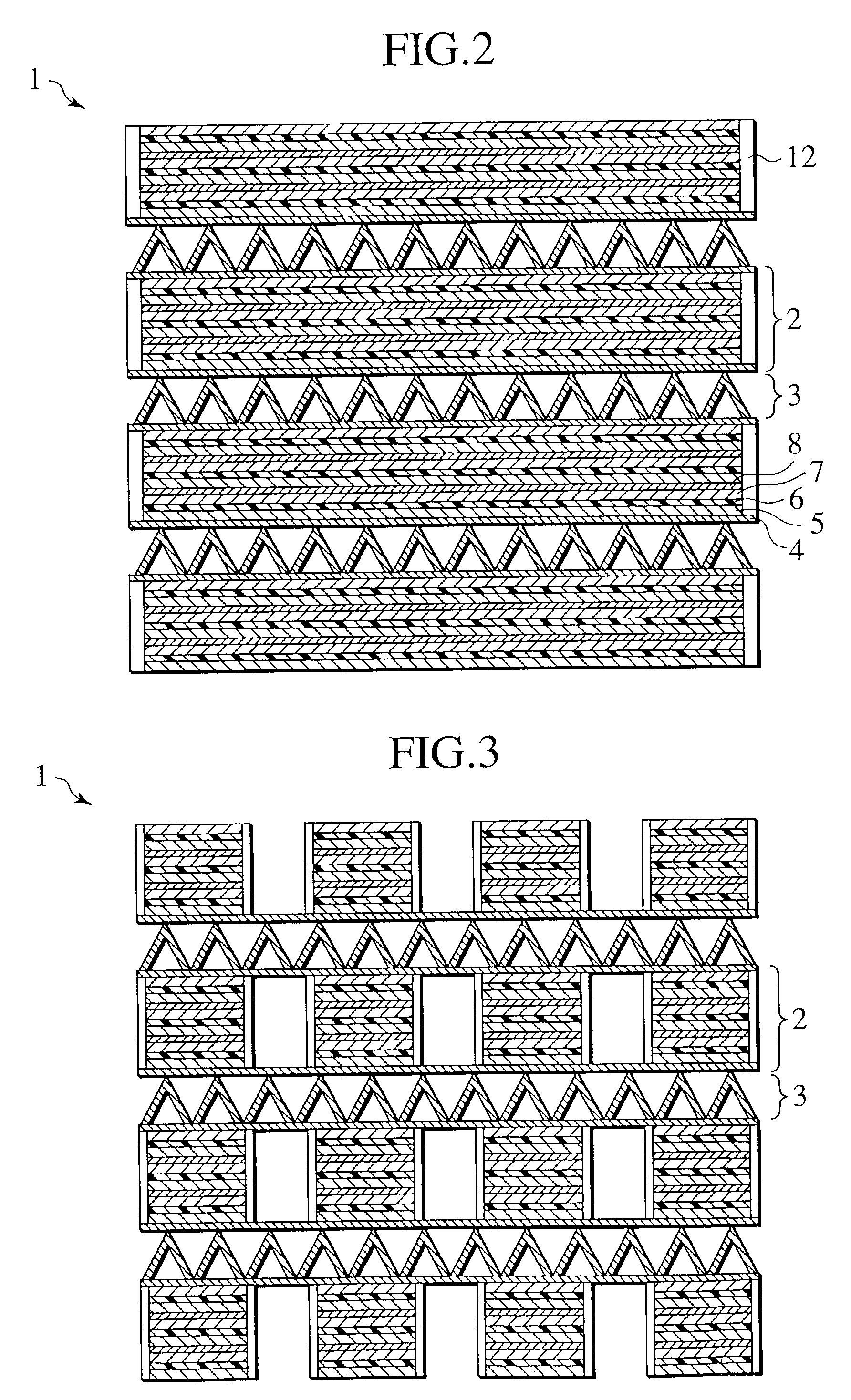
[0028]As shown in FIG. 2, the cell group 2 includes a plurality of negative electrodes 5, a plurality of solid electrolyte layers 6 and a plurality of positive electrodes 7. The negative electrodes 5, the solid electrolyte layers 6 and the positive electrodes 7 are stacked to constitute a unit cell. A plurality of the unit cells are stacked with electron conducting layers 8 sandwiched there among, thus constituting the cell group 2. Preferably, each cell group 2 is provided with insulating layers 12 on sides thereof. Desirably, the cell group 2 is thi...


PUM


Abstract

A battery system of the present invention includes one or more cell groups, each having a positive electrode, a negative electrode and a solid electrolyte layer, and one or more heat mediating structures adjacent to the cell groups. The cell groups and the heat mediating structures are alternately stacked. A solid electrolyte is applied to the electrolyte layer. The respective cell groups have a thin plate shape, and adjacent thereto, the heat mediating structures are provided.

Description

BACKGROUND OF THE INVENTION[0001]1. Field of the Invention[0002]The present invention relates to a battery system such as a lithium polymer secondary battery, and more specifically, to a battery system excellent in controllability for temperature thereof.[0003]2. Description of the Related Art[0004]In order to decrease a load to the global environment and an influence to the global warming, interest in an electric vehicle or a hybrid vehicle has been enhanced. As a power supply of such a vehicle, a demand for a high-performance secondary battery has been increased.[0005]As such a secondary battery for the electric vehicle or the hybrid vehicle, a lithium ion battery, a nickel hydrogen battery or the like has been proposed in consideration for energy density, a lifetime, an output and the like. In a high output type of the secondary battery described above, an output of 800 W / kg or more is obtained at room temperature.SUMMARY OF THE INVENTION[0006]At low temperature, internal resista...

Claims


Application Information

Patent Timeline
IPC IPC(8): H01M10/50H01M6/18H01M10/05H01M4/485H01M6/42H01M6/50H01M10/0525H01M10/0562H01M10/0565H01M10/058H01M10/48H01M10/60H01M10/613H01M10/615H01M10/625H01M10/653H01M10/654H01M10/6551H01M10/6553H01M10/6556H01M10/6563H01M10/6568H01M10/66H01M10/663
CPCH01M6/42H01M6/5038H01M10/0562H01M10/0565H01M10/5006H01M10/5016H01M10/503H01M10/5032H01M10/5055H01M10/5059H01M10/5004H01M4/505H01M4/525Y02E60/122H01M10/613H01M10/615H01M10/625H01M10/643H01M10/647H01M10/6555H01M10/6557Y02E60/10Y02P70/50
Inventor HORIE, HIDEAKIOHSAWA, YASUHIKO
Owner NISSAN MOTOR CO LTD
Learn More