
Vehicle body mount assembly

a technology for mounting assemblies and vehicles, applied in the direction of roofs, machine supports, shock absorbers, etc., can solve the problems of limited versatility of the mount assembly, construction limitations, and inability to finely tune the design of the prior art mount assembly, so as to achieve greater design flexibility

Inactive Publication Date: 2007-08-28
BASF CORP
View PDF34 Cites 48 Cited by
  • Summary
  • Abstract
  • Description
  • Claims
  • Application Information

AI Technical Summary

Benefits of technology

The invention is a mount assembly for vehicles that provides greater flexibility and design flexibility compared to previous mount assemblies. The assembly includes separate and independent components that isolate movement in multiple directions. The design of the mount assembly allows for optimal tuning of the vertical, fore, aft, and lateral spring rates. The mount assembly is particularly useful for vehicles where the frame and body are designed to move in different directions. The technical effect of the invention is a more flexible and versatile mount assembly that can be finely tuned to meet optimal design criteria.

Problems solved by technology

However, this construction has limitations.
Hence, the designs of the prior art mount assemblies cannot be finely tuned and the versatility of these mount assemblies is limited.

Method used


Image

  • Vehicle body mount assembly
  • Vehicle body mount assembly
  • Vehicle body mount assembly

Examples


Embodiment Construction

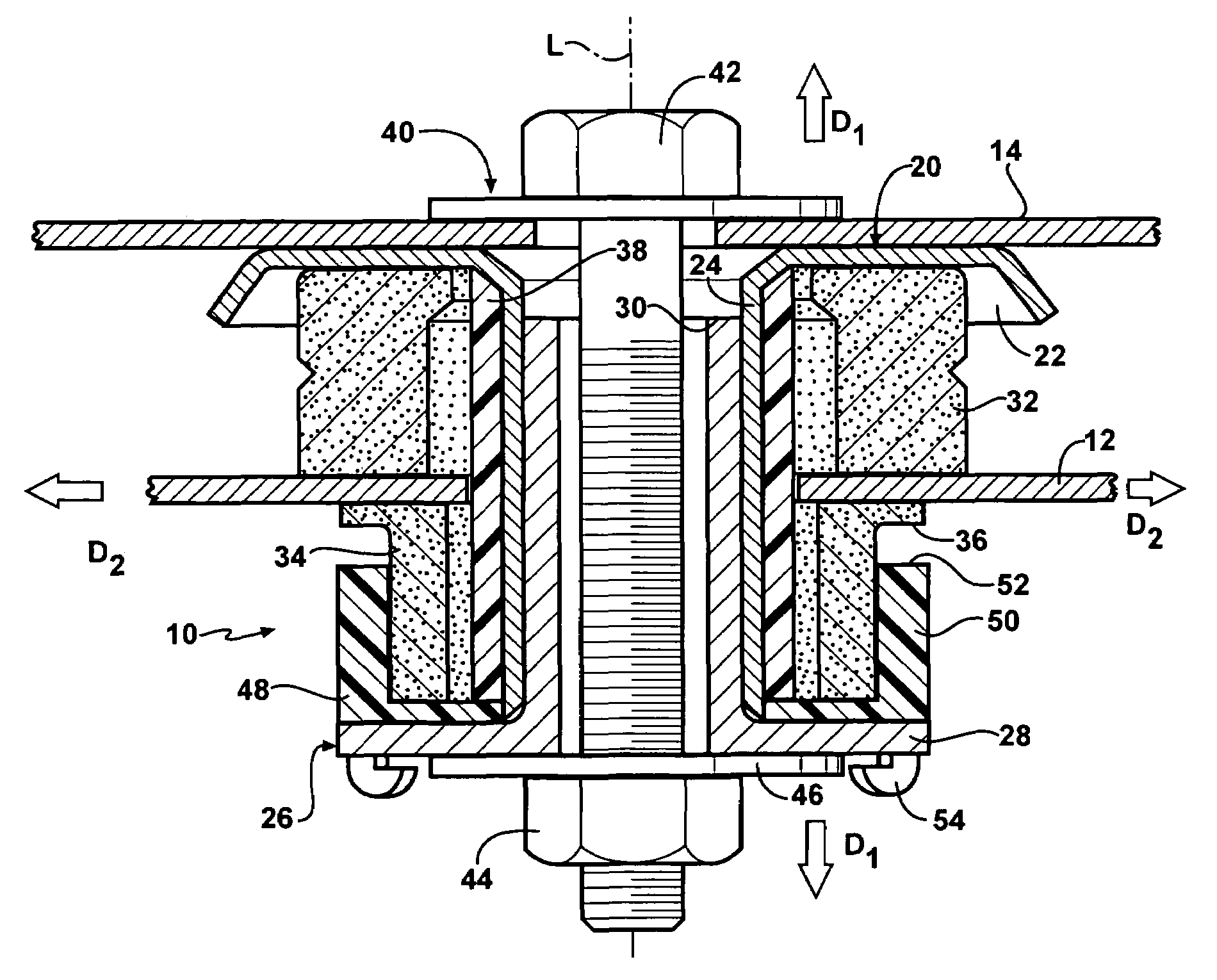
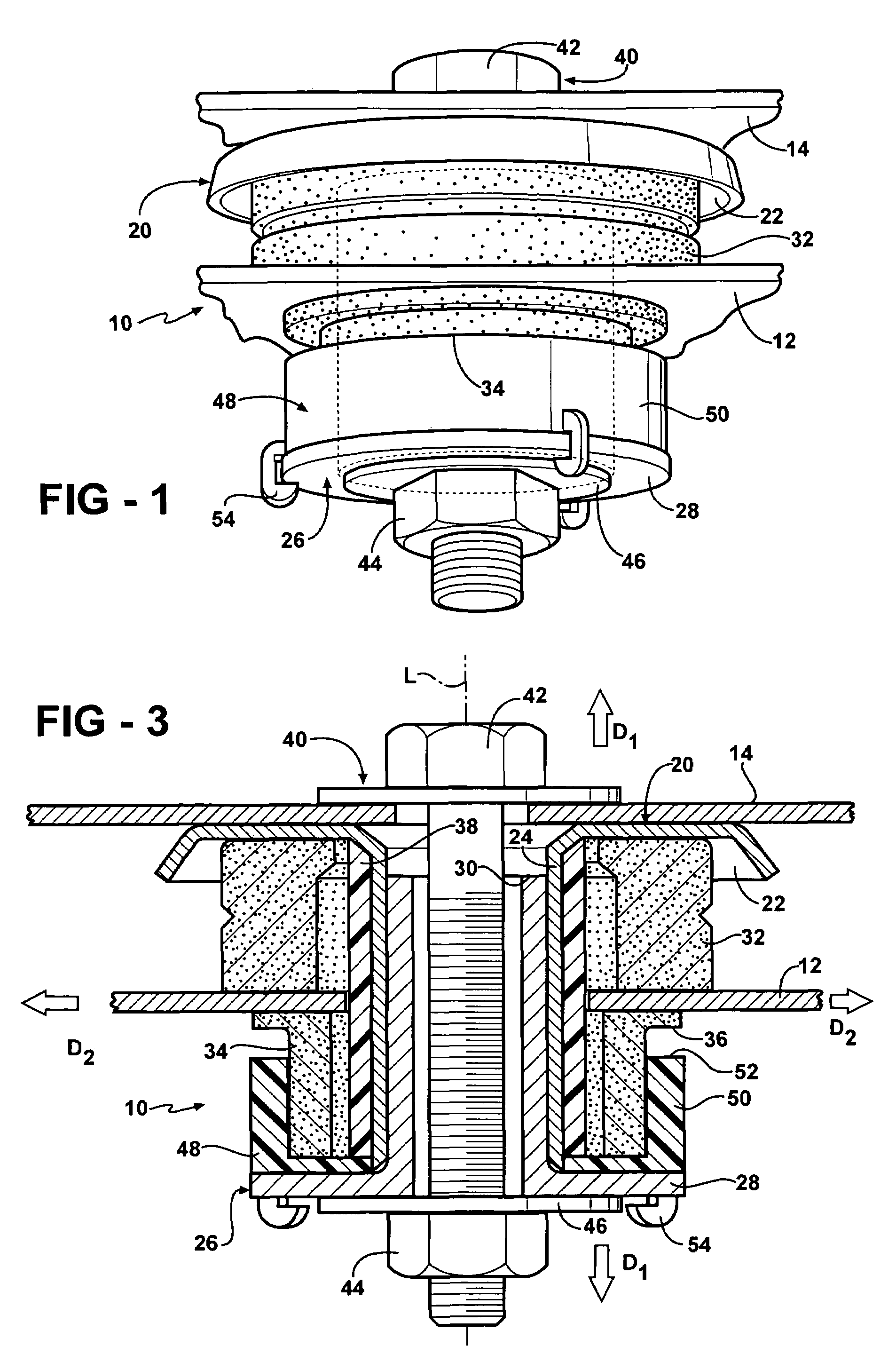
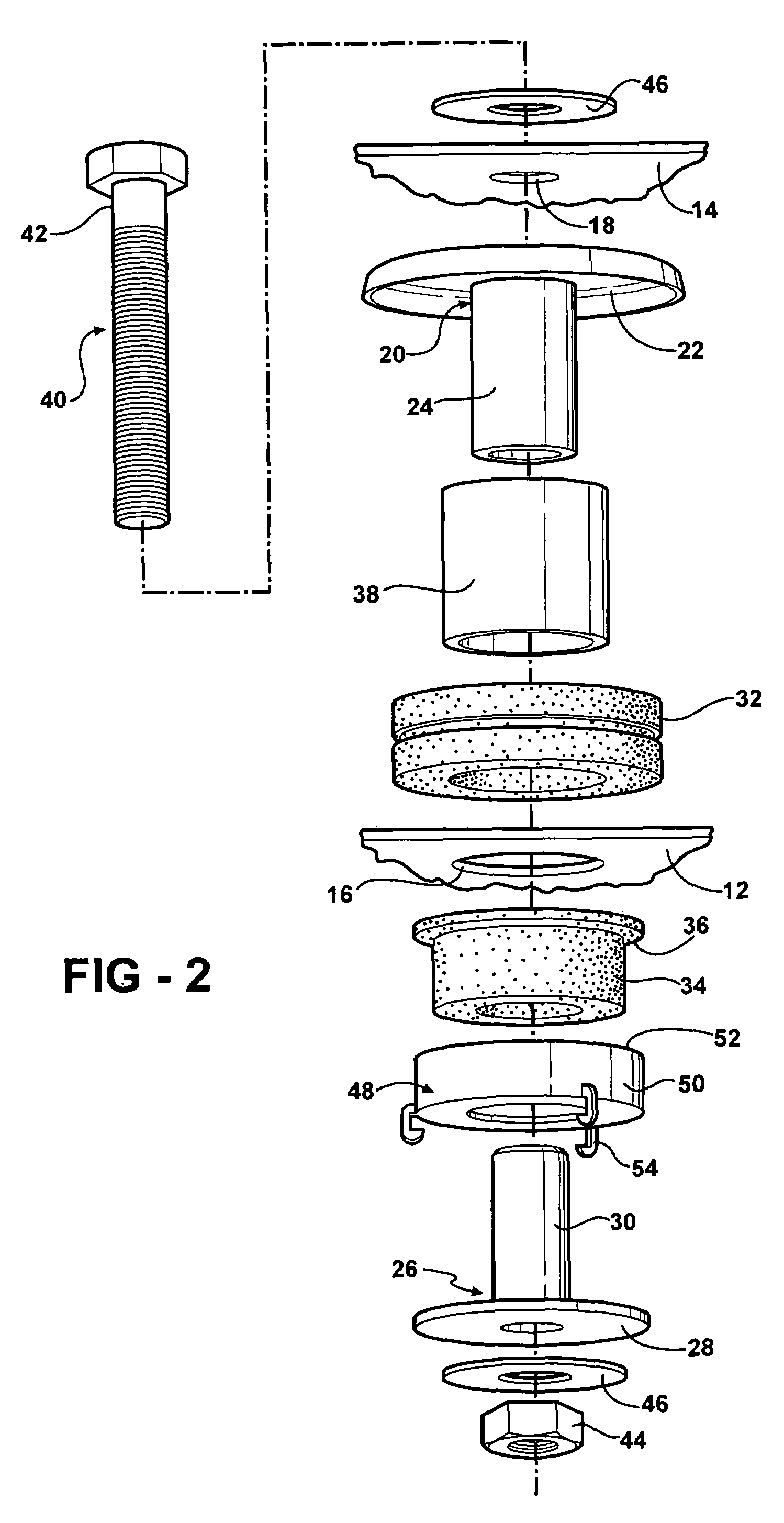
[0016]Referring to the Figures, wherein like numerals indicate like or corresponding parts throughout the several views, a mount assembly is generally shown at 10 in FIGS. 1-3. The mount assembly 10 is shown in a rest state in FIGS. 1 and 3. In the preferred embodiment, the mount assembly 10 is for use with a vehicle having a frame 12 and a vehicle body 14. Both the frame 12 and vehicle body 14 include apertures 16, 18 that will be discussed in greater detail below. For illustrative purposes, only a small fragment of the frame 12 and vehicle body 14 are shown in the Figures. The frame 12 and vehicle body 14 can be of any suitable design or configuration without deviating from the scope of the subject invention.

[0017]The mount assembly 10 includes a first carrier 20 having a first flange 22 and a first tube 24. The first carrier 20 is adapted to be coupled to the frame 12 of the vehicle with the first tube 24 extending through the aperture 16 in the frame 12. The first carrier 20 is ...


PUM


Abstract

A mount assembly having a first carrier and a first insulator disposed about the first carrier for isolating movement of a frame relative to a vehicle body in a first direction. A second carrier engages the first carrier for coupling the second carrier to the first carrier. A second insulator is disposed about the second carrier for further insolating the movement of the frame relative to the vehicle body in the first direction. A sleeve is disposed about both of the first and second carriers and is coupled to the first carrier. The sleeve is formed of an elastomeric material for isolating movement of the frame relative to the vehicle body in a second direction transverse to the first direction such that the isolation of movement about the first and second directions are accomplished by separate and independent components of the assembly.

Description

BACKGROUND OF THE INVENTION[0001]1. Field of the Invention[0002]The subject invention relates to a mount assembly for a vehicle having a frame and a vehicle body wherein movements of the frame relative to the vehicle body in various directions are isolated by separate and independent components of the mount assembly.[0003]2. Description of Related Art[0004]Mount assemblies for vehicles are well known in the art. Examples of such assemblies are shown in U.S. Pat. Nos. 3,809,427; 4,286,777; and 6,361,096. Each of these assemblies include upper and lower insulators for coupling a frame of the vehicle to a vehicle body. The insulators are typically formed of an elastomeric material such as rubber. Washers or flanges are provided on outward surfaces of the insulators and a fastener interconnects the washers or flanges to the vehicle body for sandwiching the insulators between the washers or flanges and for coupling the frame to the vehicle body. A metallic tube or sleeve can be disposed ...

Claims


Application Information

Patent Timeline
Patent Type & Authority Patents(United States)
IPC IPC(8): B60J7/00
CPCB60G99/002B60G99/004B62D24/02
Inventor DICKSON, DANIEL G.HUPRIKAR, ANANDST. HENRY, THOMAS E.DIETER, WILLIAM G.
Owner BASF CORP
Learn More