
Fast warm-up of diesel aftertreatment system during cold start

a technology of diesel aftertreatment system and cold start, which is applied in the direction of mechanical equipment, machines/engines, electric control, etc., can solve the problems of ineffectiveness, vehicle exceeding emissions limits, and controlling excess air, etc., and achieves limited effect. effect, the effect of being unable to achieve

Active Publication Date: 2007-08-28
SOUTHWEST RES INST
View PDF13 Cites 40 Cited by
  • Summary
  • Abstract
  • Description
  • Claims
  • Application Information

AI Technical Summary

Benefits of technology

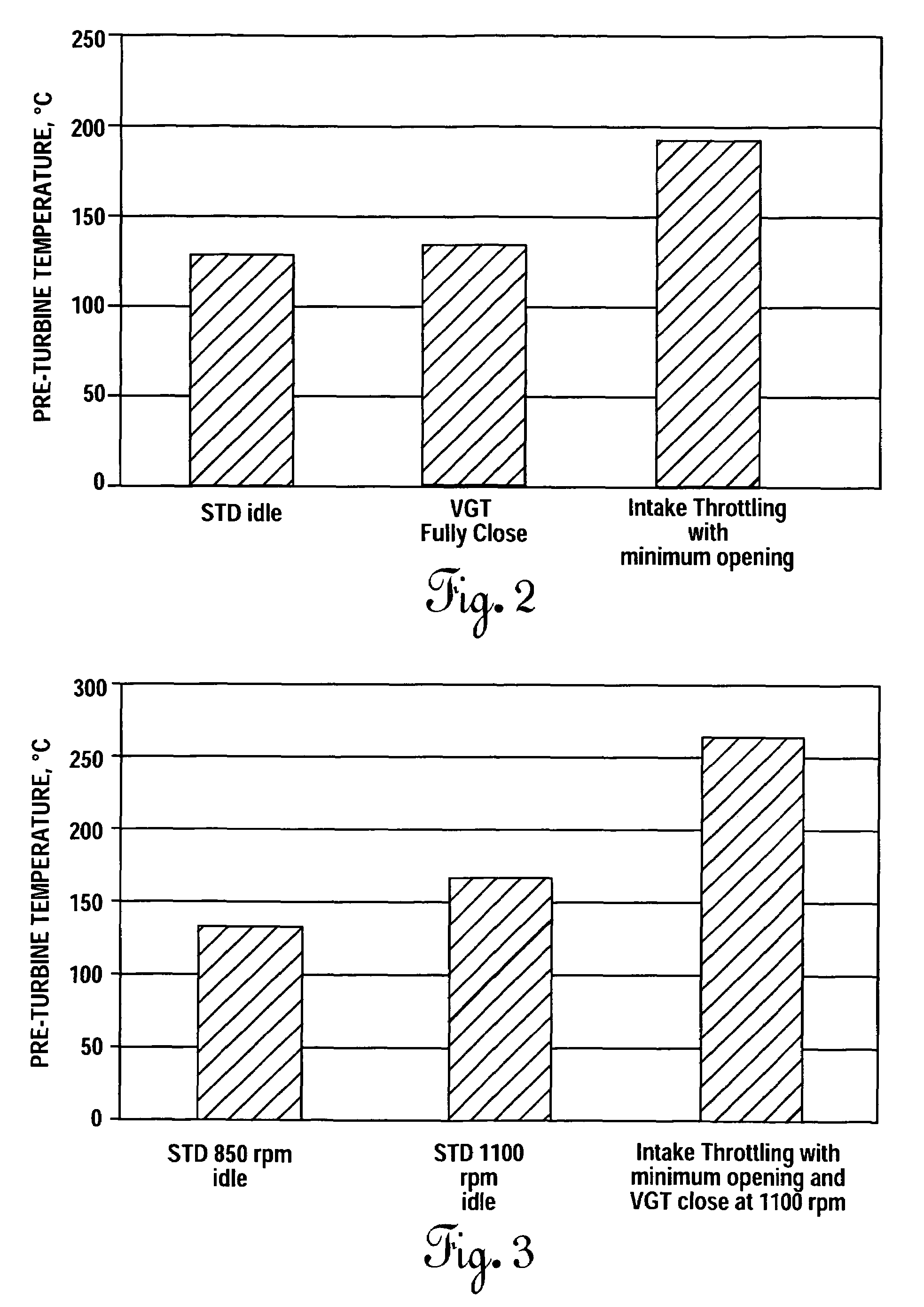
[0011]Other features of the method for the fast warm-up of an exhaust gas treatment device during cold start of a diesel engine, in accordance with the present invention, includes increasing the idle speed of the engine to a value sufficient to provide an engine-out exhaust gas temperature that is higher than the determined activation temperature of the exhaust treatment device. Also, during cold start, the turbine section of a variable geometry turbocharger associated with the engine is closed to a minimal flow position.
[0012]Another feature of the method for the fast warm-up of an exhaust gas treatment device during cold start of a diesel engine, in accordance with the present invention, includes advancing fuel injection timing when operating at idle in the low pressure premixed charge compression ignition combustion mode.

Problems solved by technology

In particular, standards set forth for model year 2007 place significant limits on NOx and particulate matter (PM) emissions that will require changes in both in-cylinder (engine-out) combustion control and exhaust treatment devices.
Although these devices currently offer the most promise for controlling exhaust emissions, they are not effective until they are heated to a predefined operating, or activation, temperature.
Fast warm-up during cold start is an important issue because if the exhaust treatment devices are not active early in the first phase of the prescribed Federal Test Procedure 75 (FTP-75) driving cycle, the vehicle will exceed the emissions limits.
However, the method proposed by Miura requires one or more delay periods after cold start to make certain determinations and adjustments.
Moreover, it has been found that controlling excess air, by itself, has limited effect on providing the high in-cylinder (engine-out) temperatures required to quickly heat exhaust treatment devices to their effective operating temperature.

Method used


Image

  • Fast warm-up of diesel aftertreatment system during cold start
  • Fast warm-up of diesel aftertreatment system during cold start
  • Fast warm-up of diesel aftertreatment system during cold start

Examples


Embodiment Construction

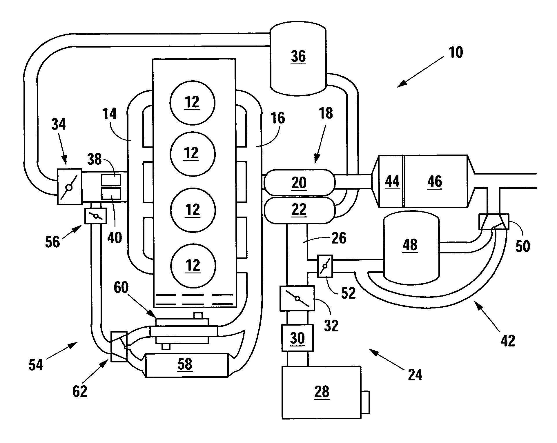
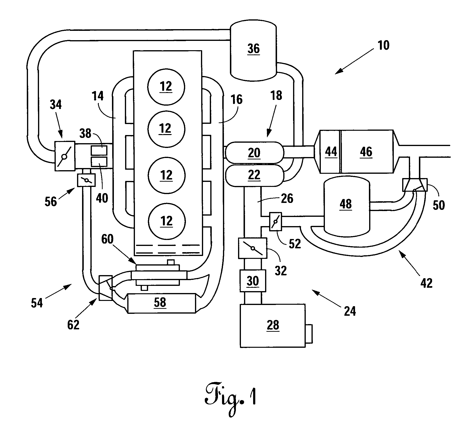
[0021]A conventional engine system suitable for illustrating the method for the fast warm-up of a diesel exhaust treatment device during cold start of a diesel engine, in accordance with the present invention, is generally identified by the reference number 10 in FIG. 1. The engine 10 has a plurality of cylinders, or compression chambers, 12, each of which are in controlled fluid communication by respective intake and exhaust valves, not shown, with an intake manifold 14 and an exhaust manifold 16. The engine 10 also has a conventional variable geometry turbocharger (VGT) 18. A turbine section 20 of the VGT 18 is in direct fluid communication with the exhaust manifold 16 and has a variable throat area which can be closed to a minimal flow position at which exhaust flow through the turbine section is severely limited. Alternatively, a waste gate, not shown, can provide a minimal flow of exhaust gas around the turbine section 20 if the turbine section is capable of being completely cl...


PUM


Abstract

Intake air is severely restricted during cold start of a diesel engine to provide high engine-out exhaust gas temperatures and quickly heat exhaust treatment devices. Cylinder pressures are maintained substantially below the pressure of the ambient atmosphere during a principal portion of the intake stroke of each combustion cycle to promote rapid fuel vaporization and higher combustion temperatures. The engine is operated in a premixed charge compression ignition combustion mode to provide a high engine-out exhaust temperature, stable combustion, and low emissions during the cold start period.

Description

[0001]Applicant claims priority under 35 U.S.C. §119 of U.S. Provisional Application Ser. No. 60 / 729,079, filed Oct. 21, 2005.BACKGROUND OF THE INVENTION[0002]1. Technical Field[0003]This invention relates generally to a method for increasing engine-out temperature during cold start of a diesel engine to provide fast warm-up of exhaust aftertreatment system components, and more particularly to such a method that includes reducing the mass of the intake air charge and the intake manifold pressure of low-pressure premixed charge compression ignition dominated combustion during cold start.[0004]2. Background Art[0005]The U.S. Environmental Protection Agency (EPA) has set very stringent emissions standards for diesel engines. The standards are directed at reducing smog-causing emissions from all diesel engines, including off-road vehicles, trucks, buses, recreational vehicles, and motor homes. In particular, standards set forth for model year 2007 place significant limits on NOx and par...

Claims


Application Information

Patent Timeline
Patent Type & Authority Patents(United States)
IPC IPC(8): F02M7/12F02M7/00
CPCF01N3/00F02D9/02F02D41/0002F02D41/0245F02D41/0255F02D41/064F02D41/3035F02M25/0707F02M25/0709F02M25/0718F02M25/0728F02M25/0731F02M25/0732F02M25/0738F02M25/074F02B1/12F02B3/06F02B29/0406F02B37/00F02D41/0065F02D41/403F02D2009/0249Y02T10/128Y02T10/14Y02T10/26Y02T10/42F02M26/05F02M26/06F02M26/15F02M26/24F02M26/25F02M26/28F02M26/33F02M26/35Y02T10/12Y02T10/40
Inventor NUANG, YIQUN
Owner SOUTHWEST RES INST
Learn More