Optical underwater acoustic sensor

a technology of optical underwater and acoustic sensor, which is applied in the field of optical underwater acoustic sensor, can solve the problems of limited receiver aperture and bandwidth of these devices, inaccurate data, and limited air-water boundary, and achieve the effect of improving acoustic underwater sensor, low cost and simple installation

Inactive Publication Date: 2007-08-21
THE UNITED STATES OF AMERICA AS REPRESENTED BY THE SECRETARY OF THE NAVY
View PDF5 Cites 13 Cited by
  • Summary
  • Abstract
  • Description
  • Claims
  • Application Information

AI Technical Summary

Benefits of technology

[0015]It is a further object of this invention to provide an acoustic sensor that is relatively simple to install and relatively low cost.
[0016]This invention meets these and other objectives related to improved acoustic underwater sensors by providing an acoustic sensor for detecting the acoustic pressure placed upon a structure in an underwater environment. The sensor provides an optically reflective material adhered to one side of the structure. The optical coating is used to enhance the optical reflection of light back to the sensor. Although diffuse and specular reflectors would allow detection, retro-reflectors provide a high optical return over a wide range of incident angles. A laser interferometer provides laser beams to a plurality of points across the reflective material. The laser interferometer has receiving optics to receive the reflection of the laser beams back from the plurality of points. Within the laser interferometer, a reference laser beam is maintained. The laser interferometer also includes signal processing capability to compare the frequency modulation of the reference laser beam to the frequency modulation of the reflected beams. Thus, allowing the sensor to determination the vibration of the reflective material (and the adhered structure), and, in turn, the acoustic pressure on the structure.

Problems solved by technology

However, the receiver aperture and bandwidth of these devices are limited.
However, such an air-water boundary may only be achieved on the surface of a supercavitating object.
While such a configuration allows a user to obtain acoustic data from the outer hull of the submarine, such data may be inaccurate due to the normal placement of a transducer between the inner and outer hull surfaces of a submarine, which can create interference due to the acoustics reflecting between the outer hull and the transducer.
Also, installation of a separate panel between the inner and outer hulls may be cumbersome and costly.

Method used


Image

  • Optical underwater acoustic sensor
  • Optical underwater acoustic sensor
  • Optical underwater acoustic sensor

Examples


Embodiment Construction

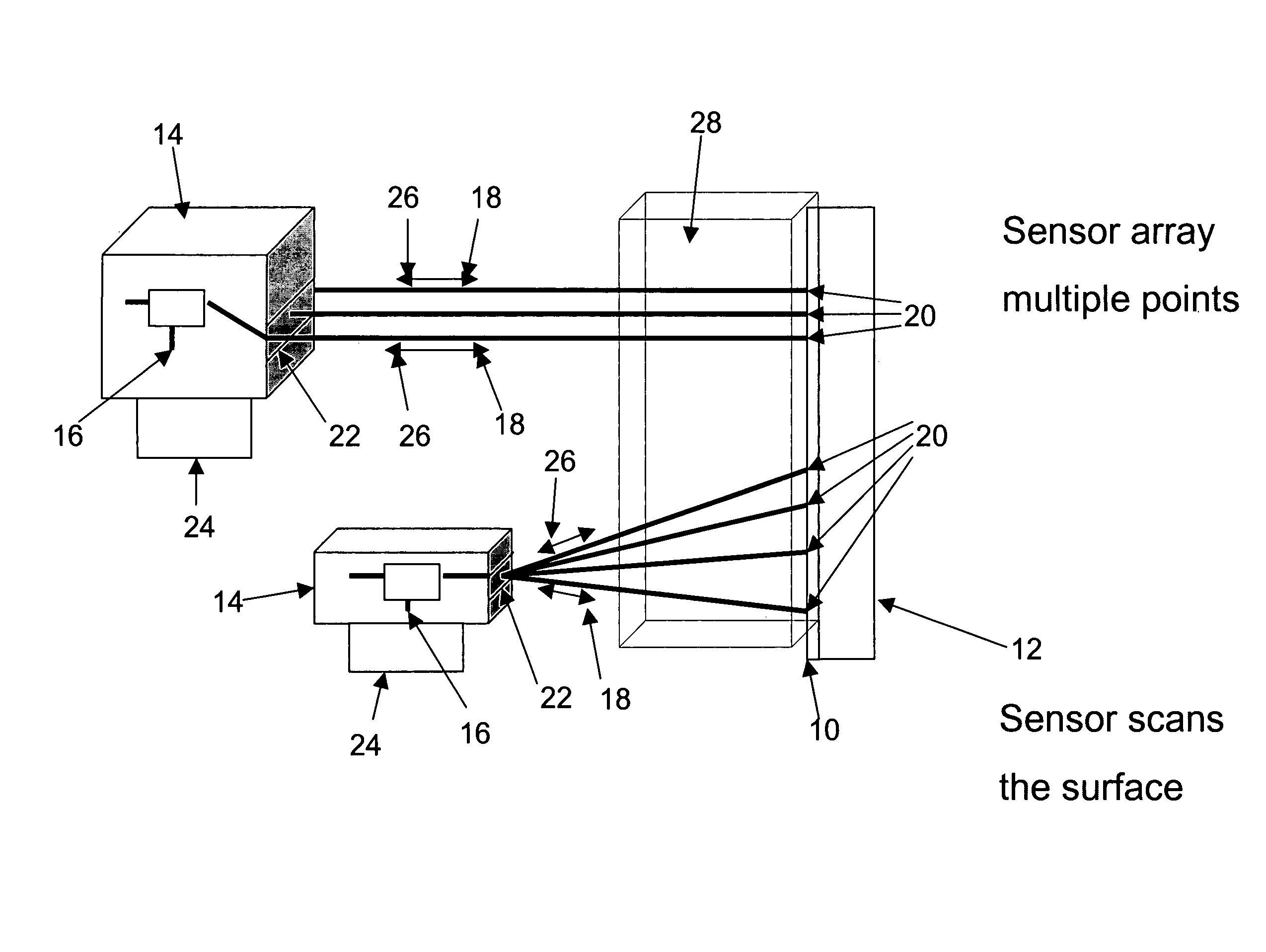
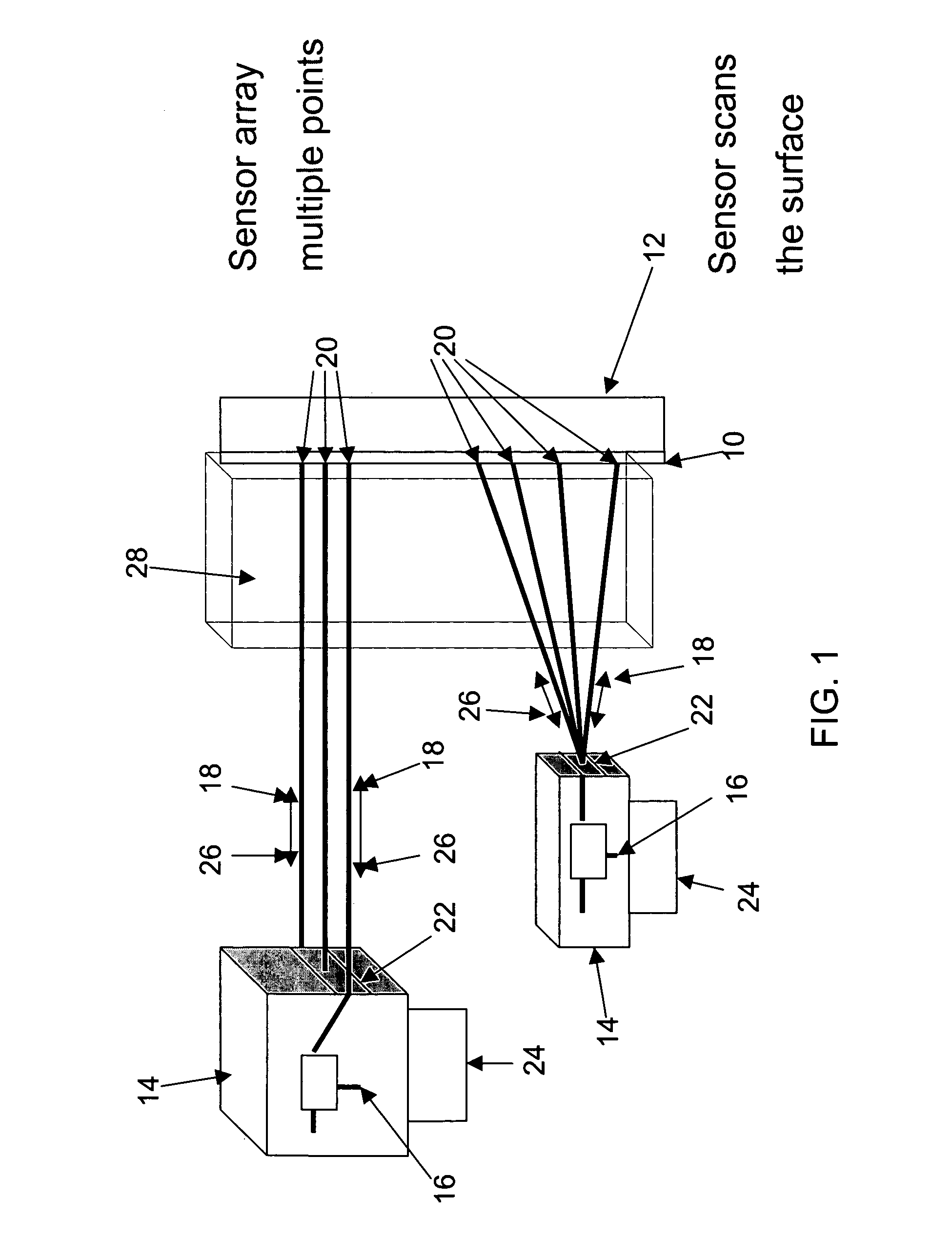
[0020]The invention, as embodied herein, comprises an improved acoustic sensor for use in providing the acoustic signature associated with underwater structures such as ship hulls, submarine hulls, and torpedo casings. The acoustic sensor of the present invention employs similar principles to those described in U.S. Pat. No. 6,188,644, which is incorporated by reference herein.

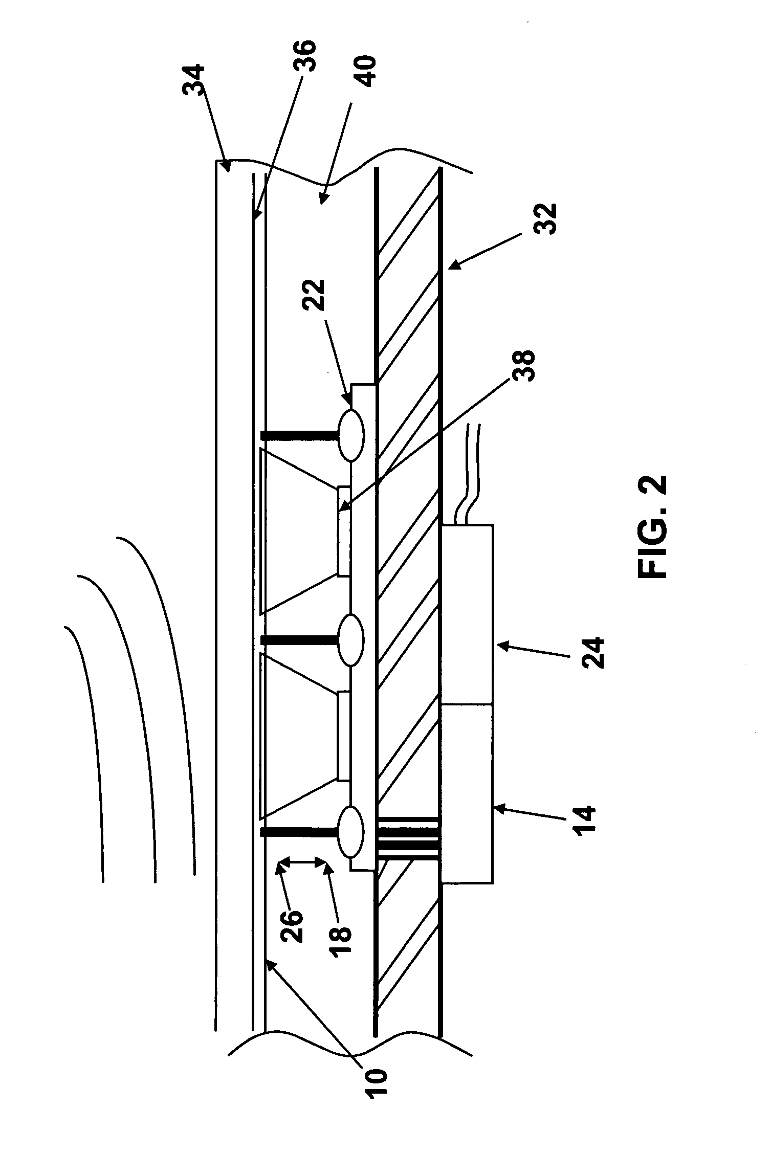
[0021]In general, the present invention is an acoustic sensor used in underwater applications. The sensor comprises a reflective material adhered to the inner side of a structure, such as an outer submarine hull. A laser interferometer is placed on the side of the structure with the reflective material. The laser interferometer sends a plurality of laser beams, in sequence or all at one time, to a plurality of points across the retro-reflective material. The laser beams reflect back to the interferometer, which captures the reflected beams using receiving optics. The phase modulation of the reflected laser bea...


PUM


Abstract

An acoustic sensor used in underwater applications. The sensor includes a reflective material adhered to a structure, such as an outer submarine hull or any marine vessel hull. A laser interferometer is placed on the side of the structure with the reflective material. The laser interferometer sends a plurality of laser beams, in sequence or all at one time, to a plurality of points across the retro-reflective material. The laser beams reflect back to the interferometer, which captures the reflected beams using receiving optics. The phase modulation of the reflected laser beams is compared to a reference laser beam within the interferometer to obtain the vibration velocity characteristics of the hull surface structure. Since the reflective material is adhered to the structure, the structure vibration is the same as the vibration of the reflective material. From this vibration, the acoustic pressure associated with the structure may be calculated.

Description

STATEMENT OF GOVERNMENT INTEREST[0001]The invention described herein may be manufactured and used by or for the Government of the United States of America for governmental purposes without payment of any royalties thereon or therefor.BACKGROUND OF THE INVENTION[0002]1. Field of the Invention[0003]This invention relates in general to sensors, more particularly to acoustic sensors, and most particularly to acoustic sensors for underwater applications.[0004]2. Description of the Related Art[0005]In the past, acoustic transducers and hydrophones have been used to convert underwater acoustical energy into electrical signals. These are typically ceramic-based products that work on the principle of either piezoelectricity or magnetostriction. These devices are typically capable of both transmitting and detecting acoustic pressure in the water. However, the receiver aperture and bandwidth of these devices are limited.[0006]Laser-based techniques for detection of sound for underwater applica...

Claims


Application Information

Patent Timeline
Patent Type & Authority Patents(United States)
IPC IPC(8): G01B11/02
CPCG01H9/00H04R1/44H04R23/008
Inventor ANTONELLI, LYNN T.WALSH, KENNETH M.GAUTHIER, BENOIT G.
Owner THE UNITED STATES OF AMERICA AS REPRESENTED BY THE SECRETARY OF THE NAVY
Why Eureka
Try Eureka