
Wear monitor for turbo-machine

a wearable monitor and turbo-machine technology, applied in the direction of machines/engines, mechanical apparatus, instruments, etc., can solve the problems of considerable cost savings and time efficiencies of the system, and achieve the effect of considerable cost savings and time efficiencies

Inactive Publication Date: 2007-08-21
SIEMENS ENERGY INC
View PDF18 Cites 23 Cited by
  • Summary
  • Abstract
  • Description
  • Claims
  • Application Information

AI Technical Summary

Benefits of technology

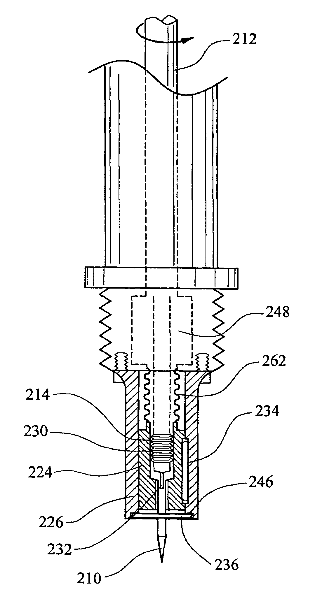
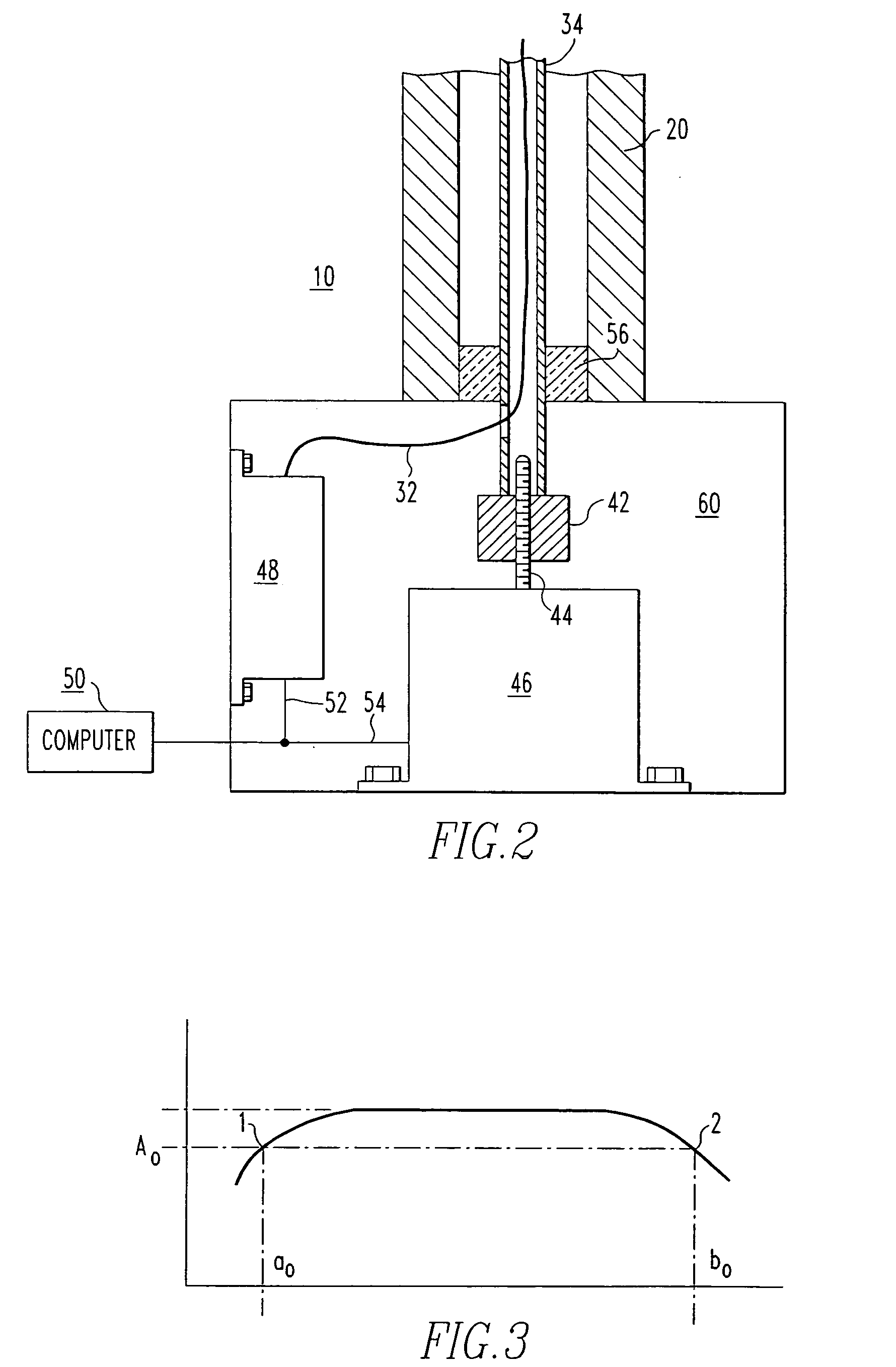
"This patent describes a measurement device for determining wear in a machine, such as a turbo-machine. The device consists of an electromechanical head assembly with a housing, a touch point for contacting the surface of the machine, and a drive device for moving the touch point. The device can measure the distance between adjacent machine components and compare it with other measurements to identify wear. The device can be attached to an insertion probe that is attached to the machine, and it can measure the distance between surfaces that are parallel and perpendicular to the shaft of the machine. The device can also include an identification device for identifying measurements with a particular location on the machine. The invention allows for the attachment of multiple insertion probes to a single turbine engine, which saves time and money."

Problems solved by technology

Such a system enjoys considerable cost savings and time efficiencies.

Method used


Image

  • Wear monitor for turbo-machine
  • Wear monitor for turbo-machine
  • Wear monitor for turbo-machine

Examples

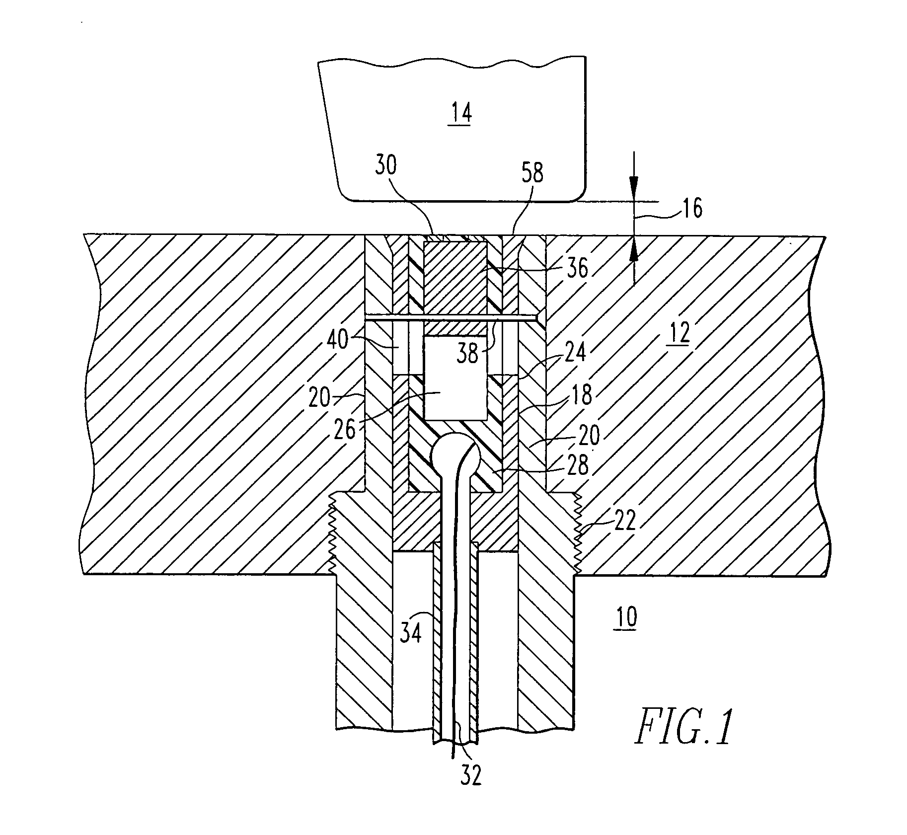

Embodiment Construction

[0027]Throughout this specification, the term “turbo-machine” is used to refer to a device that includes rotating and stationary airfoils contained within a stationary casing used for the purpose of imparting energy into or extracting energy from a fluid passing over the airfoils.

[0028]FIG. 1 illustrates the forward sensing portion of a blade clearance monitoring system 10 for monitoring the clearance 16 between a turbine blade, such as a compressor blade 14 and a stationary component of the turbine such as a blade ring 12. A very small eddy current search coil 30 is employed to provide a short range and sensitive indication by means of a discrete voltage signal level output, of the proximity of the blade tip and search coil in the order of 0.010 inch (0.254 mm). A search coil 30 that can be employed for this purpose preferably has an inner diameter from between 0.020 to 0.050 inch (0.508-1.27 mm). The search coil is mounted at an end of a short throw insertion probe 18. A short thr...


PUM

PropertyMeasurementUnit
inner diameteraaaaaaaaaa
range of movementaaaaaaaaaa
thermal response timeaaaaaaaaaa

Abstract

A measurement device for measuring the wear of turbo-machine components to reduce the likelihood of component failure while a turbine-machine is at load. The measurement device is capable of measuring and calculating a distance between surfaces while the turbo-machine is at load. The distance may be compared with a measurement taken of the same location at another time to determine wear of a surface remote from the location of the measurement. The measurement device may be configured such that multiple measurements may be made on a single turbine engine by moving the measurement device from location to location.

Description

CROSS REFERENCE TO RELATED APPLICATIONS[0001]This application is a continuation-in-part of U.S. patent application Ser. No. 10 / 320,791, filed Dec. 16, 2002 now U.S. Pat. No. 6,949,922, which is a continuation-in-part of U.S. patent application Ser. No. 10 / 158,954, filed May 31, 2002 now U.S. Pat. No. 6,661,222.FIELD OF THE INVENTION[0002]This invention is directed generally to measurement devices, and more particularly to measurement devices useful for determining wear in turbine engines at operating load.BACKGROUND[0003]The clearance between the stationary seals of a combustion turbine or compressor turbine and the tips of the rotating blades therein must not be so great as to permit an excessive amount of fluid to pass there between, and thereby reducing the efficiency of the turbine. On the other hand, clearances cannot be too small because high centripetal loading and high temperatures may cause blades to lift or to grow radially. Such blade lifting or radial growth can cause bl...

Claims


Application Information

Patent Timeline
Patent Type & Authority Patents(United States)
IPC IPC(8): G01B7/14F01D21/00H01F5/00
CPCF01D21/003G01B7/14F05D2270/305
Inventor TWERDOCHLIB, MICHAEL
Owner SIEMENS ENERGY INC
Learn More