[0007]The present invention has for its object to provide a device for heating liquids, the heating element of which, in contrast to the prior art, can be activated in a reliable manner and at any desired moment.
[0011]In addition, it may be advantageous if the boiling sensor and / or the overheating sensor both comprise at least one
thermistor. A
thermistor is a temperature-sensitive electrical resistance, examples being NTC and PTC resistors which are obtainable in many variants. A
thermistor is in principle more robust than for instance a
bimetal switch. A
significant difference from a
bimetal switch is that a thermistor does not contain any
moving parts that are essential for operation. A thermistor can further have more compact dimensions. Both properties increase the freedom in design of the device. A device according to the invention with one or more thermistors is relatively very simple and inexpensive. A further
advantage of applying thermistors is that the
switching time of a thermistor can be very short. Such a short
switching time has the
advantage that a device will operate quickly (and thus relatively safely). In addition, it is advantageous that the thermistors function at low voltages and with low amperages; these need (and in practice will) not be incorporated in a main current circuit. Another
advantage of the thermistors functioning at low voltages and with low amperages is that they can be embodied with a very small
mass, and can thereby also operate with a very short time
delay (
low mass inertia). A short
delay during switching (short
switching time) results in the chance of overheating (consider for instance a blown fuse) being reduced considerably. A short time
delay is also referred to as a “small
time constant”. Conversely, it is also possible to make use of small
bimetal switches which likewise do not have to be incorporated in a main current circuit. It is precisely this non-inclusion of the thermistors (and / or small bimetal switches) in the main current circuit that provides extra freedom in the design of the device in which they are incorporated. A further additional advantage of applying thermistors is that it is possible to apply so-called multi-track elements, whereby a thermistor can for instance be paired with a plurality of surfaces of a heating element. It is not therefore the heating element as a whole that is safeguarded, but detection takes place on a smaller scale, on separate parts of the heating element. This also results in a quicker and more precise detection.
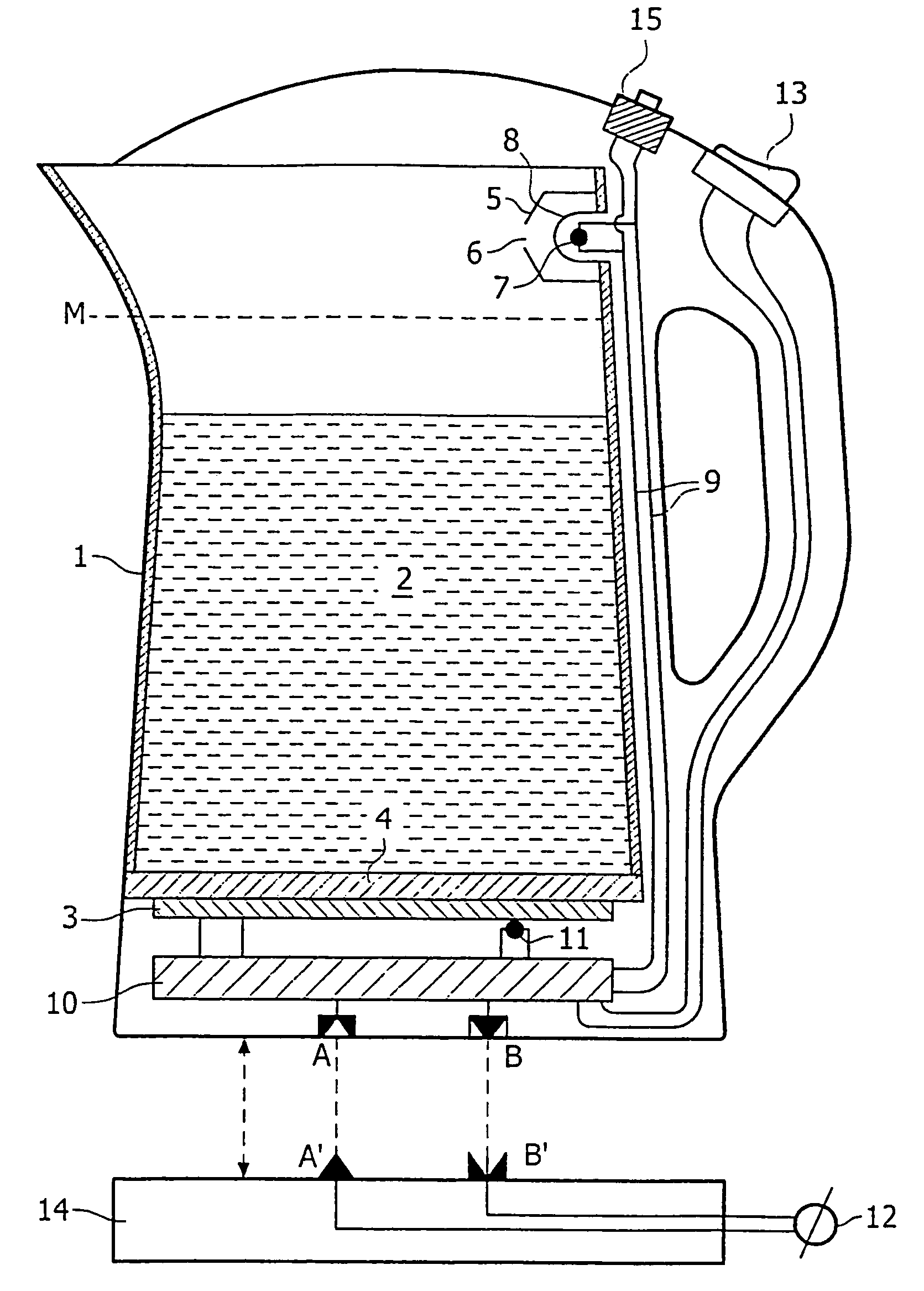
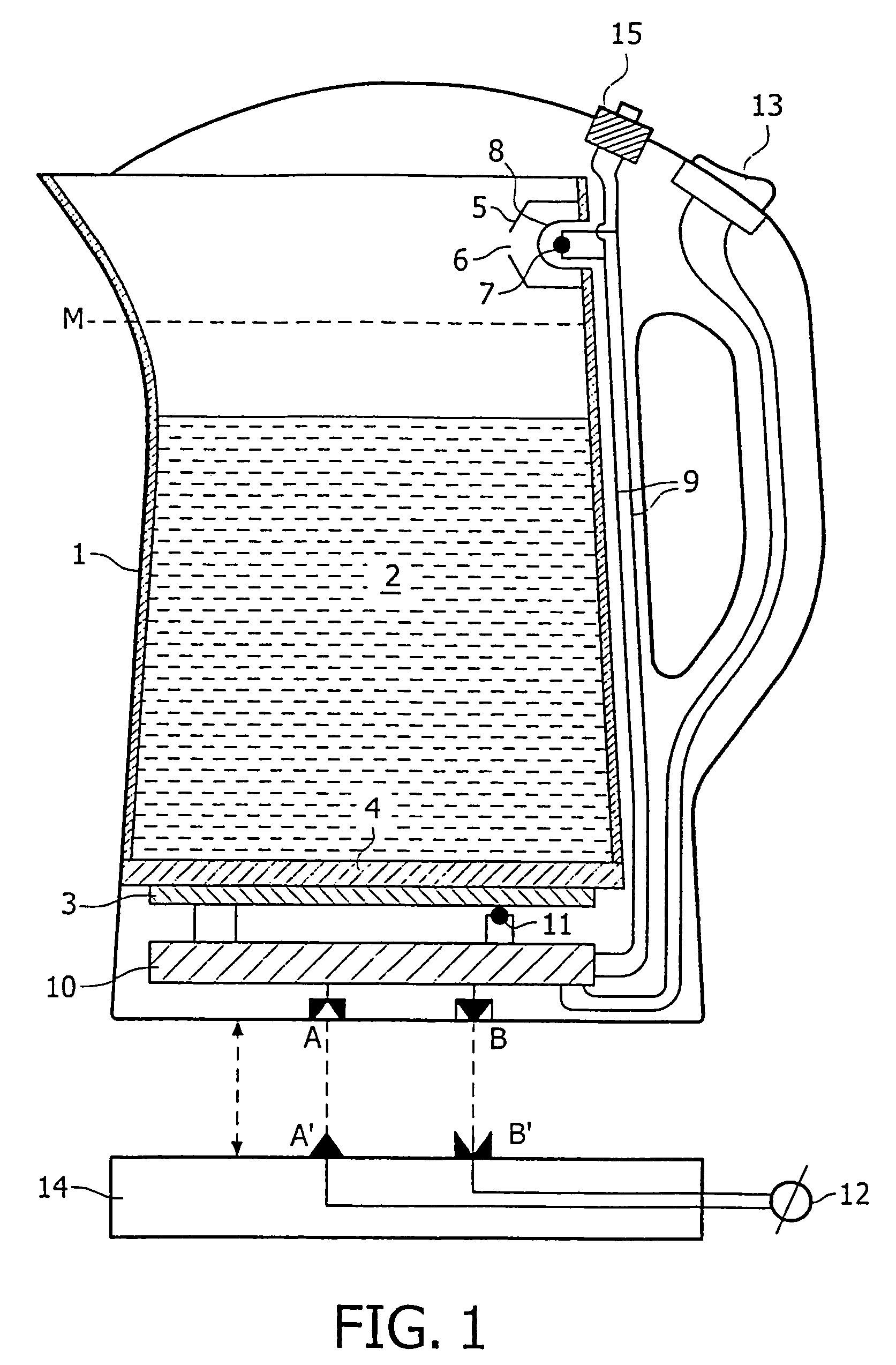
[0013]It is advantageous if the boiling sensor is thermally connected to the inner side of the liquid container at a location
lying above a determined maximum liquid level of the liquid container. The boiling sensor will hereby substantially detect the temperature of the vapour above the liquid, thereby avoiding premature interruption of the power supply when non-homogeneous temperature fluctuations occur in the heated liquid. The vapour comes into contact with the sensor and thereby causes a temperature increase in the sensor, which results in detection of the boiling temperature. The temperature above the liquid will only rise significantly when the liquid boils and thus produces a relatively large amount of vapour. The above technical measure has the advantage that a relatively less accurate, inexpensive sensor can be applied for detection of the boiling temperature of the liquid.
[0014]In a non-limitative preferred embodiment, the boiling sensor is placed in a chamber connected to the liquid container such that the chamber is in communication with the liquid container above the maximum liquid level. The boiling sensor will hereby substantially measure the temperature of the vapour above the liquid. Because the boiling sensor is placed in the chamber, the boiling detection can be more reliable than outside the chamber, where fluctuations in temperature and splashes of boiling liquid make detection less precise.
[0015]It is advantageous when the boiling sensor is screened in medium-tight manner from the liquid container. On the one hand this prevents adverse effects of liquid in the liquid container on the boiling sensor and the
electronic circuit connected thereto. On the other hand material from the boiling sensor is prevented from entering the liquid container (for instance through wear or being dissolved) and thus contaminating the liquid. The screening can be designed for instance by incorporating the boiling sensor in the line of a wall of the liquid container, although forms can also be envisaged where the boiling sensor is screened by an anti-splash plate, or where the boiling sensor is positioned in a tubular or
capsule-like cover. The medium-tight material used for the screening can comprise for instance plastic,
metal or
ceramic.
[0016]In a particular non-limitative preferred embodiment of the present invention, the boiling sensor is located outside the liquid container, and the boiling sensor is in
thermal contact with the inner side of the liquid container via a thermal conductor. The thermal conductor can for instance take the form of a wire or strip, preferably manufactured from a
metal such as
copper or
aluminium. The thermal conductor can be partly covered with a thermally insulating layer, for instance in the form of an insulating strip, wrapping, tube or sleeve. This can make the heat conduction through the thermal conductor to the boiling sensor more efficient and heat is prevented from being conducted directly to the thermal conductor via the wall of the liquid container. The use of the thermal conductor provides an increased freedom of design for the device according to the invention because the sensor does not have to be situated at the measuring position, and can therefore be positioned at many locations. The interposing of the thermal conductor also provides improved options for protecting the boiling sensor from the adverse effects of liquid or liquid vapour.


