
Mobile gas separator system and method for treating dirty gas at the well site of a stimulated gas well

a technology of stimulated gas well and separator, which is applied in the direction of separation process, membrane, borehole/well accessories, etc., can solve the problems of limiting co2 content, corroding hydrogen sulfide, and hazardous to humans, and delivery gas specifications typically limit water vapor conten

Inactive Publication Date: 2007-08-07
STRAHAN RONALD L
View PDF39 Cites 21 Cited by
  • Summary
  • Abstract
  • Description
  • Claims
  • Application Information

AI Technical Summary

Problems solved by technology

For example, pipelines typically limit CO2 content due to its corrosive properties.
Similarly, hydrogen sulfide is corrosive and is hazardous to humans if inhaled, so it is also subject to restrictions (typically ≦4 ppm) by pipeline companies.
In addition, delivered gas specifications typically limit water vapor content.
Because of these common contaminants, raw gas produced immediately after stimulation rarely meets typical delivered gas specifications.
However, in most wells, the gas stream will soon become pipeline quality if the well is flared or vented for a brief period.
Flaring has a detrimental effect on the environment because it releases the contaminants into the air.
In addition, flaring wastes a significant amount of natural gas and other hydrocarbons.
Neither of these options is economically feasible for cleaning the gas produced after a stimulation procedure in a well where only the initial post-stimulation gas is unmarketable.

Method used


Image

  • Mobile gas separator system and method for treating dirty gas at the well site of a stimulated gas well
  • Mobile gas separator system and method for treating dirty gas at the well site of a stimulated gas well
  • Mobile gas separator system and method for treating dirty gas at the well site of a stimulated gas well

Examples


Embodiment Construction

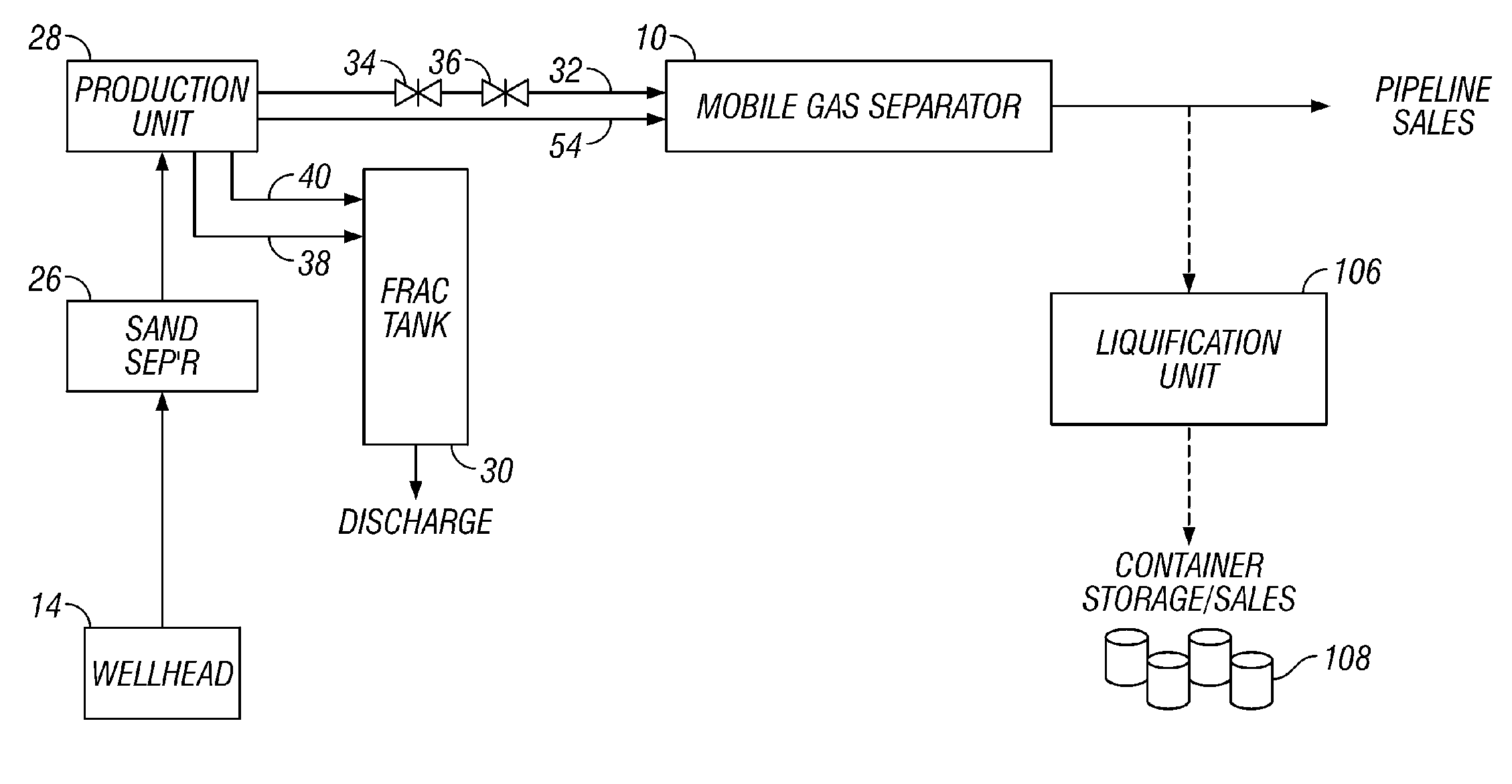
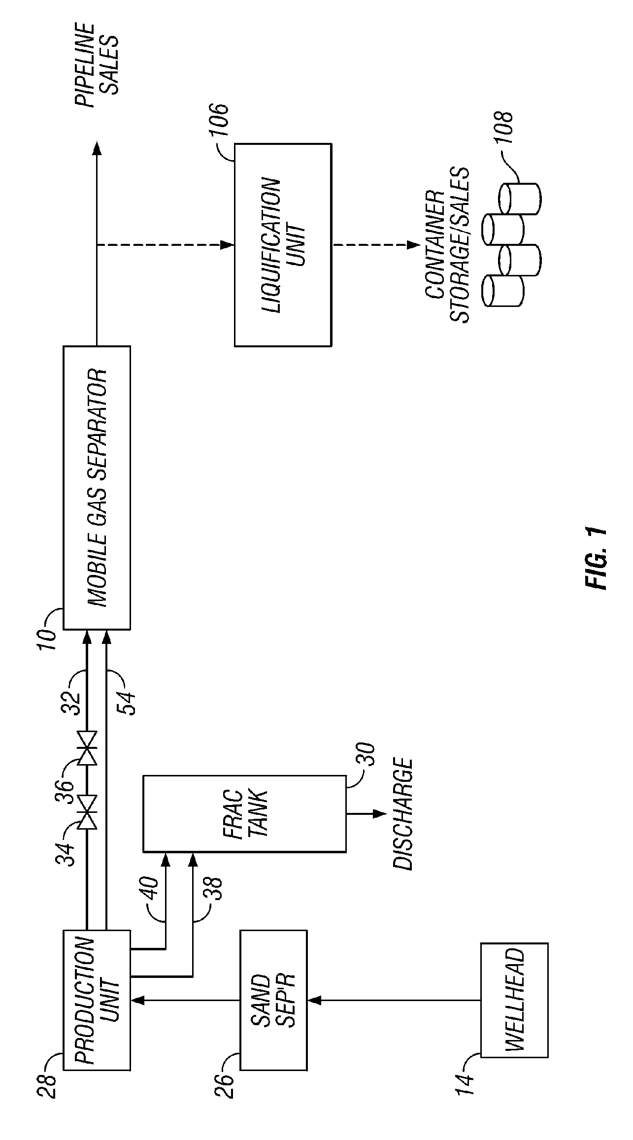
[0011]With reference now to the drawings in general and to FIG. 1 in particular, there is shown therein a mobile gas separator system constructed in accordance with one preferred embodiment of the present invention and designated generally by the reference numeral 10. The system is designed for temporary, short-term use at a gas well immediately after stimulation, when the initial raw gas is dirty or heavily contaminated. In particular, the system 10 is designed to be moved from well to well. In this way, a small mobile system is available to operators to treat and sell the initial post-stimulation gas instead of flaring or venting it to the atmosphere.

[0012]As used herein, “immediately after stimulation” and similar expressions refer to the period following completion of a stimulation procedure during which the well is producing gas that is not marketable. As used herein, “marketable gas” refers to natural gas that meets pipeline company delivered gas standards.

[0013]Turning now to...


PUM

PropertyMeasurementUnit
temperatureaaaaaaaaaa

Abstract

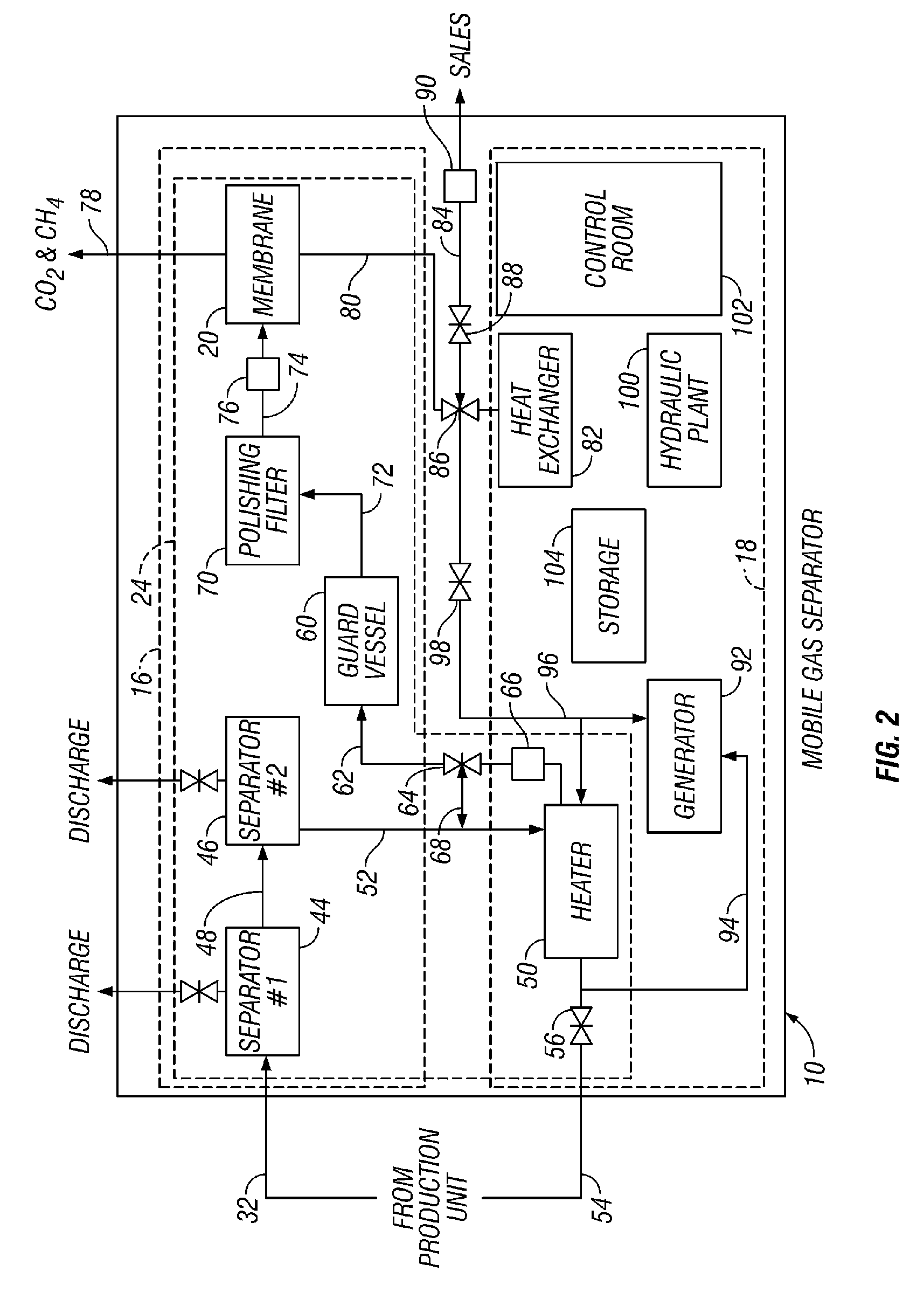
A method and mobile system for cleaning dirty gas from a newly stimulated gas well. The entire system is supported on a trailer or other mobile support so that it can be driven from well site to well site for short-term, post-stimulation use only. The system comprises a gas separator, such as a membrane separator. The system also includes a pretreatment assembly for preparing the gas for the gas separator. The pretreatment assembly may include separators, a heater, a guard vessel and a polishing filter. A chiller or heat exchanger cools the treated gas to a marketable temperature. A generator and a hydraulics plant provide power to the system. Each mobile system will be designed to treat gases with widely different operating conditions varying from well to well.

Description

[0001]This application is a continuation of application Ser. No. 10 / 695,610, entitled “Mobile Gas Separator System and Method for Treating Dirty Gas at the Well Site of a Stimulated Gas Well,” filed Oct. 28, 2003, now U.S. Pat. No. 6,955,704 B1, issued Oct. 18, 2005 and the contents of that application are incorporated herein by reference.FIELD OF THE INVENTION[0002]The present invention relates to methods and devices for cleaning “dirty” gas from a recently stimulated gas well.BACKGROUND OF THE INVENTION[0003]When a gas well is stimulated, the initial raw gas emitted at the wellhead is a mixture of natural gas, other hydrocarbons and contaminates, such as hydrogen sulfide (H2S), water (H2O) and carbon dioxide (CO2). This so-called “dirty” gas may also contain particulate matter, such as sand and particles of drilling fluids.[0004]Each pipeline company has its own set of natural gas quality specifications that delivered gas must meet. For example, pipelines typically limit CO2 conte...

Claims


Application Information

Patent Timeline
Patent Type & Authority Patents(United States)
IPC IPC(8): B01D46/46B01D53/02B01D53/22E21B43/00C10L3/10E21B43/34
CPCB01D53/22B01D63/00C10L3/10C10L3/102E21B43/34B01D2257/304B01D2257/504B01D2257/80B01D2313/18B01D2313/22B01D2313/38C10G2300/4062Y02C10/08Y02C10/10Y02C20/40B01D2313/221E21B43/35
Inventor STRAHAN, RONALD L.
Owner STRAHAN RONALD L
Learn More