Magnetoresistive head

a magnetoresistive head and head technology, applied in the field of magnetoresistive heads, can solve the problems of reducing the recording area per bit, weakening the generated magnetic field, and the current cip spin-valve mr sensor cannot meet the demand for the distance between the magnetic shields of 40 nm or smaller, and achieves high reproduction output signals and stable output high-quality reproduction signals

Inactive Publication Date: 2007-07-31
FUJITSU LTD
View PDF7 Cites 0 Cited by
  • Summary
  • Abstract
  • Description
  • Claims
  • Application Information

AI Technical Summary

Benefits of technology

[0021]Accordingly, it is an object of the present invention to provide a MR head that can restrain generations of Barkhausen noises and obtain high reproduction output.
[0028]The present invention controls the magnetization of the MR coating using the current magnetic field that results from the current that flows between the third electrode terminal and one of the first and second electrode terminals, restrains generations of the Barkhousen noises, and provides high reproduction output signals. In addition, the present invention provides fine adjustments to the bias current strength for each head, and thus stably outputs high-quality reproduction signals after the MR head is produced.
[0029]The inventive structure does not require the magnetization control coatings to be provided at both sides of the MR coating in the track width direction, thus remarkably facilitating the manufacture process and dramatically improving the yield.

Problems solved by technology

The high-recording density of a magnetic disc drive reduces a recording area per bit, and weakens a generated magnetic field.
As the recording bit becomes shorter on the record carrier, the current CIP spin-valve MR sensors cannot meet a demand for the distance between the magnetic shields of 40 nm or smaller.
The MR head that utilizes the MR coating disadvantageously generates Barkhausen noises and greatly fluctuates reproduction outputs when the MR coating does not have a single magnetization.
However, the magnetization control using the antiferromagnetic layer layered on the MR coating needs to make orthogonal to each other the pinning directions between the antiferromagnetic coating used for the MR coating and the antiferromagnetic coating used for the magnetization control, and is problematic in that the coating development is difficult.
In addition, since the antiferromagnetic coating is layered on the MR coating, it is difficult to reduce a distance between the magnetic shields.
Therefore, it is very difficult to stably manufacture the magnetization control coating with good yield and to stably obtain the effect.
When the magnetic shields are provided at both sides of the MR coating in the track width direction for the high recording density, the magnetization control coatings cannot be provided at both sides of the MR coating in the track width direction.

Method used


Image

  • Magnetoresistive head
  • Magnetoresistive head
  • Magnetoresistive head

Examples


first embodiment

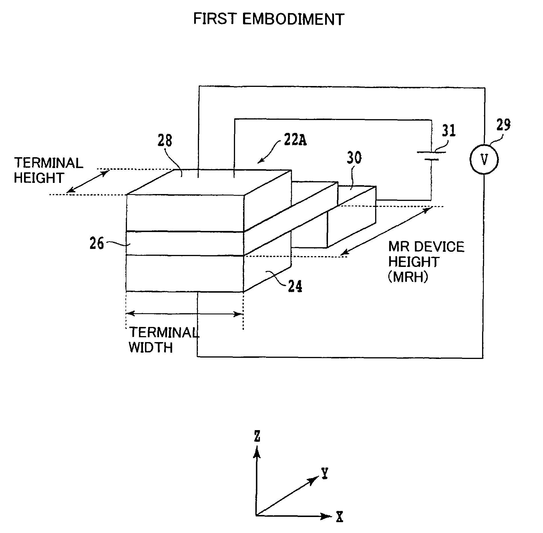
[0053]FIG. 3 shows a schematic perspective view of a MR head 22A according to the present invention, and omits first and second magnetic shields. 24 denotes a first electrode terminal that is made, for example, of Cu or a combination of Cu and Au, and a third electrode terminal 30 is provided apart from the first electrode terminal 24 at a side opposite to the entry surface (i.e., ABS surface) of the carrier's magnetic field, of the first electrode terminal 24. The third electrode terminal 30 is also made, for example, of Cu or a combination of Cu and Au.

[0054]A MR coating 26 is located on the first and third electrode terminals 24 and 30, and a second electrode terminal 28 is located on the MR coating 26 opposite to the first electrode terminal 24. The second electrode terminal 28 is also made, for example, of Cu or a combination of Cu and Au.

[0055]The first and second electrode terminals 24 and 28 are connected to a sense current source 29, and the sense current source 29 applies ...

second embodiment

[0065]FIG. 7 shows a schematic perspective view of a MR head 22B according to the present invention, and omits first and second magnetic shields. In the MR head 22B of the instant embodiment, the first electrode terminal 24, the MR coating 26′, and the second magnetic shield 28 have substantially the same length in the device height direction.

[0066]A third electrode terminal 30′ is provided at a side opposite to the entry surface (i.e., ABS surface) of the carrier's magnetic field, of the MR coating 26′, and is electrically connected to the MR coating 26′. The third electrode terminal 30′ is isolated from the first and second electrode terminals 24 and 28.

[0067]The first and second electrode terminals 24 and 28 are connected to the sense current source 29, and the first and third electrode terminals 24 and 30 are connected to the bias current source 31. The sense current and the bias current flow in almost the same direction along the in-plane perpendicular direction of the first el...


PUM

PropertyMeasurementUnit
thicknessaaaaaaaaaa
thicknessaaaaaaaaaa
distanceaaaaaaaaaa

Abstract

A magnetoresistive head includes a first magnetic shield, a first electrode terminal arranged on the first magnetic shield at an entry side of a magnetic field from a carrier, a third electrode terminal that is spaced from the first electrode terminal, and arranged on the first magnetic shield at a side opposite to the entry side of the magnetic field from the carrier, a magnetoresistive coating arranged on the first and third electrode terminals, a second electrode terminal that is arranged on the magnetoresistive coating, and opposed to the first electrode terminal, a second magnetic shield arranged on the second electrode terminal, and a sense current source connected to the first and second electrode terminals, which applies sense current in a direction perpendicular to a coating surface of the magnetoresistive coating.

Description

[0001]This application claims the right of priority under 35 U.S.C. §119 based on Japanese Patent Application No. 2004-178407, filed on Jun. 16, 2004, which is hereby incorporated by reference herein in its entirety as if fully set forth herein.BACKGROUND OF THE INVENTION[0002]The present invention relates generally to magnetoresistive heads used for magnetic storage, such as a magnetic disc drive and a magnetic tape.[0003]Along with recent smaller and higher density productions of magnetic disc drives decrease a floating amount of a head slider, and demand contact recording / reproducing that has an extremely low floating height or requires a slider to contact a record carrier.[0004]A conventional magnetic inductive head deteriorates reproduction output as the circumferential speed, which is a relative speed between a head and a medium, decreases in a small magnetic disc. Magnetoresistive (“MR”) heads, which provide a reproduction output that does not depend upon the circumferential ...

Claims


Application Information

Patent Timeline
Patent Type & Authority Patents(United States)
IPC IPC(8): G11B5/39G11B5/127G11B5/33
CPCG11B5/3903G11B5/3912
Inventor KONDO, REIKOSHIMIZU, YUTAKATANAKA, ATSUSHI
Owner FUJITSU LTD
Why Eureka
Try Eureka