
Dispenser with lock

a technology of dispenser and lock, which is applied in the field of hand-operable dispensers, can solve the problems of actuators being lost or inadvertently discarded, actuators being bumped and perhaps partially depressed or actuated, and unprotected, and achieve the effect of increasing resistan

Active Publication Date: 2007-07-31
SEAQUIST PERFECT DISPENSING FOREIGN INC
View PDF116 Cites 96 Cited by
  • Summary
  • Abstract
  • Description
  • Claims
  • Application Information

AI Technical Summary

Benefits of technology

"The present invention provides a dispensing assembly that can be used in either a pump dispensing package or an aerosol valve dispensing package. The assembly includes a dispenser cartridge with a stem and an actuator for dispensing fluent material. The actuator has a force-bearing actuation region that can be subjected to an actuation force to depress the actuator and actuate the dispensing assembly. A locking sleeve is rotatably mounted around both the stem and the actuator and can be rotated to lock or unlock the dispensing assembly. The assembly also includes a trigger mechanism for moving the actuator, which has a finger-grippable lever portion extending from it. The trigger engages the top of the actuator and provides the user with some mechanical advantage to move the actuator. The actuator has a nozzle or spout, but the nozzle or spout does not engage the locking sleeve in the locked or unlocked condition. The locking mechanism is easily operable and provides a tactile sensation when rotated between the locked and unlocked positions. The locking mechanism can also provide a click or similar sound when moved. The invention provides a more convenient and user-friendly dispensing assembly for fluent materials."

Problems solved by technology

However, even a hood can be knocked off of the package, and that would leave the actuator unprotected such that the actuator could be inadvertently bumped and perhaps partially depressed or actuated.
In those designs where a hood is employed, the disadvantages are that such a hood is an additional component that must be provided by the manufacturer, and the hood must subsequently be removed from the pump by the user (and perhaps retained by the user for subsequent replacement on the pump).
When the clip is removed, it could possibly be lost or inadvertently discarded.
Such a removable locking plug also could be lost or inadvertently discarded, or even purposely stolen.

Method used


Image

  • Dispenser with lock
  • Dispenser with lock
  • Dispenser with lock

Examples


first embodiment

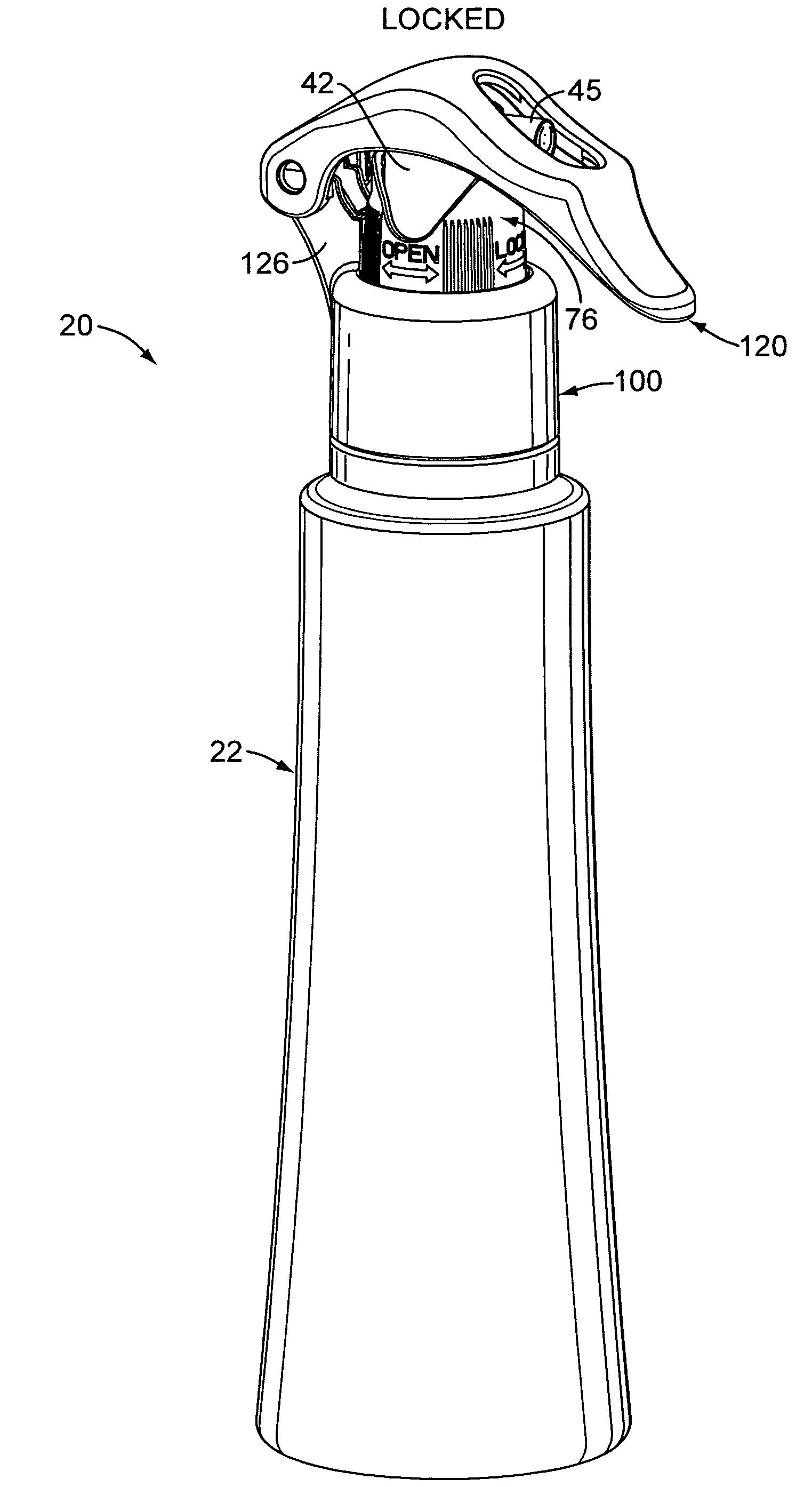
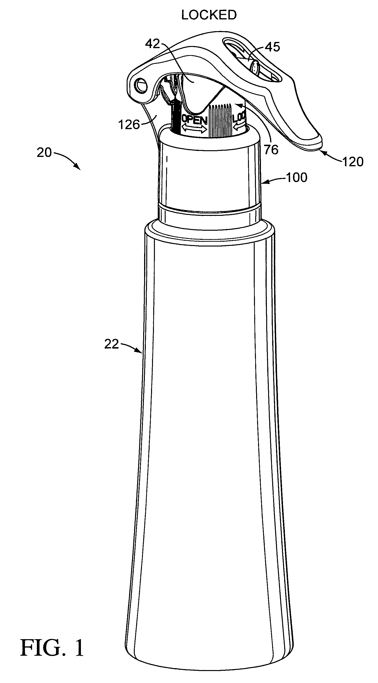
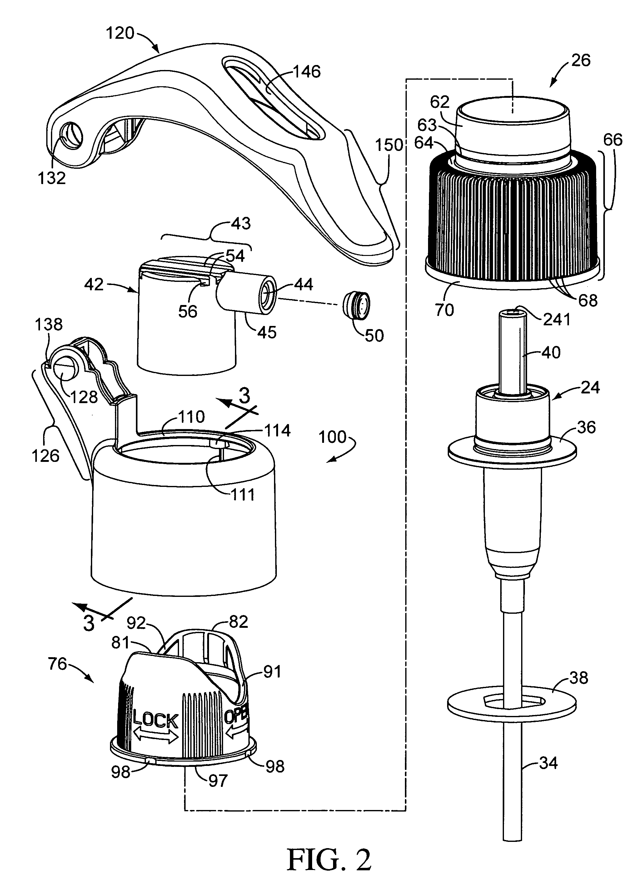
[0070]FIG. 1 illustrates a package 20 employing a hand-operable dispensing assembly of the present invention in which the assembly is in the form of a dispensing pump assembly installed on a container 22. FIG. 2 illustrates a typical pump or dispensing pump cartridge 24 that may be employed as part of the assembly on the container 22 and which is adapted to be mounted with a closure 26 in the mouth of the container 22.

[0071]The container 22 is adapted to hold a product (e.g., a liquid (not shown)) below the pump cartridge 24. Typically, the upper end of the container 22 and a portion of the pump assembly can be conveniently held in the user's hand.

[0072]The container 22 may be made of any suitable material, such as metal, glass, or plastic. As shown in FIGS. 6 and 8, the container 22 can have a reduced diameter neck 28 (FIG. 6) with a rim 29 defining a mouth or opening 30 into which the pump cartridge 24 is inserted.

[0073]The exterior of the container neck 28 typically defines threa...

fifth embodiment

[0168]In the fifth embodiment illustrated in FIGS. 29-37, the trigger 120C is similar, but not identical, to the trigger 120 shown in FIG. 2 and described above with reference to the embodiment illustrated in FIGS. 1-14.

[0169]The fifth embodiment trigger 120C differs from the first embodiment trigger 120 in that the trigger 120C includes a trigger lock stop in the form of a downwardly extending arm 500C (FIG. 36). The arm 500C of the trigger 120C includes two spaced-apart sidewalls 502C joined by a cross wall 504C (FIGS. 32 and 37). As can be seen in FIG. 36, the arm 500C defines a generally right-angle notch 508C. As can be seen in FIG. 30, the notch 508C is adapted to receive either of the upper abutment edges of the locking sleeve 76C when the locking sleeve 76C is shown in a locking orientation (FIGS. 29 and 30). In FIG. 29, the locking sleeve 76C is in a first rotated position which defines a first locking orientation wherein the first abutment edge 81C is directly below, and e...


PUM


Abstract

A dispensing assembly is provided for a container of fluent material. A hand-operable dispenser cartridge is adapted to be mounted to the container. An actuator, which may include a nozzle or spout, is mounted on the cartridge. A locking sleeve is mounted around the cartridge and has an upper abutment edge and a recess. The locking sleeve can be rotated between a first rotated position preventing actuation of the dispensing assembly and a second rotated position permitting actuation of the dispensing assembly.

Description

CROSS REFERENCE TO RELATED APPLICATION[0001]This application is a continuation-in-part of the U.S. utility patent application Ser. No. 11 / 176,896 filed Jul. 7, 2005, which is a continuation-in-part of the U.S. design patent application Ser. No. 29 / 218,428, filed Nov. 29, 2004 now U.S. Pat. No. D,525,123.TECHNICAL FIELD[0002]The present invention relates generally to a hand-operable dispensing package for fluent material, typically as a spray. The invention more particularly relates to an assembly of components for mounting a dispenser to a container in a way that can selectively permit or prevent actuation of the dispenser. The invention can be incorporated in a system employing either an aerosol dispensing valve or dispensing pump.BACKGROUND OF THE INVENTION AND TECHNICAL PROBLEMS POSED BY THE PRIOR ART[0003]Hand-operable or finger-operable dispensers (including, for example, both dispensing pumps and aerosol dispensing valves) are typically adapted to be mounted on hand-held conta...

Claims


Application Information

Patent Timeline
Patent Type & Authority Patents(United States)
IPC IPC(8): B67B5/00B67D7/58
CPCB05B11/3014B05B11/3057B05B11/3059B65D83/201B65D83/22B05B11/1014B05B11/1057B05B11/1059
Inventor WALTERS, PETER J.KSIAZK, JASON A.CHO, SEAN H.HALLMAN, PAUL E.WERNER, JONATHAN D.BRAUN, CRAIG
Owner SEAQUIST PERFECT DISPENSING FOREIGN INC
Learn More