Eureka AIR delivers breakthrough ideas for toughest innovation challenges, trusted by R&D personnel around the world.

Step ladder apparatus

Inactive Publication Date: 2012-09-11
HOP DARYL J
View PDF39 Cites 12 Cited by
  • Summary
  • Abstract
  • Description
  • Claims
  • Application Information

AI Technical Summary

Benefits of technology

[0019]In another preferred embodiment, the step assemblies include a opposing bracket members coupled to a step member. The opposing bracket members are attached to the frame with a fastener. Each of the opposing bracket members include a surface configuration, and, the sides of the frame assembly include mating surface configurations, wherein the surface configurations of the opposing bracket members couple to the mating surface configurations of the frame assembly. In turn, rotation of the respective bracket member and the frame relative to each other is minimized.
[0023]In another aspect of the invention, the invention comprises a method of coupling a step ladder apparatus to a stake pocket comprising the steps of: inserting a frame assembly into a stake pocket, the frame assembly having a plurality of step assemblies coupled to the frame assembly and positioned below the stake pocket; positioning the frame assembly so that a first flange at a top end thereof overhangs a wall of the stake pocket; providing a wedge having a base and a second flange; and inserting a base of the wedge into the stake pocket between the frame assembly and an opposing side wall of the stake pocket such that the flange overhangs the stake pocket, so that the first flange and the flange of the wedge cooperate to releasably couple the frame assembly to the stake pocket and to preclude downward movement of the frame assembly relative to the stake pocket.

Problems solved by technology

While these have provided some utility, there have been drawbacks.
Many of these step ladders require permanent attachment, and as such are of limited applicability.
Other step ladders are difficult to attach to the trailer, or lack the required stability necessary to provide confidence and useability.
Still others are cumbersome and difficult to store.

Method used


Image

  • Step ladder apparatus
  • Step ladder apparatus
  • Step ladder apparatus

Examples


Embodiment Construction

[0038]While this invention is susceptible of embodiment in many different forms, there is shown in the drawings and described herein in detail a specific embodiment with the understanding that the present disclosure is to be considered as an exemplification and is not intended to be limited to the embodiment illustrated.

[0039]It will be understood that like or analogous elements and / or components, referred to herein, may be identified throughout the drawings by like reference characters. In addition, it will be understood that the drawings are merely schematic representations of the invention, and some of the components may have been distorted from actual scale for purposes of pictorial clarity.

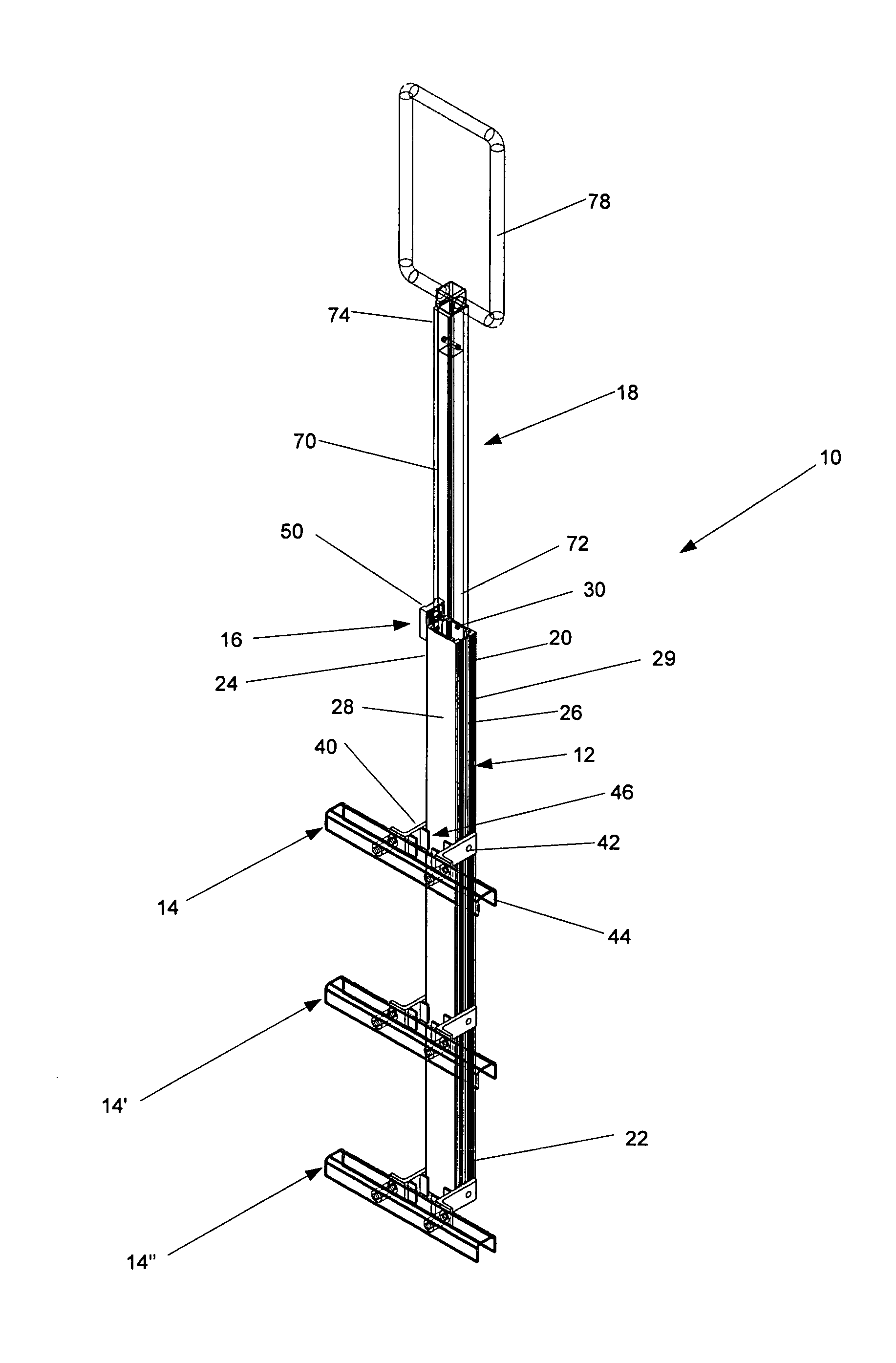
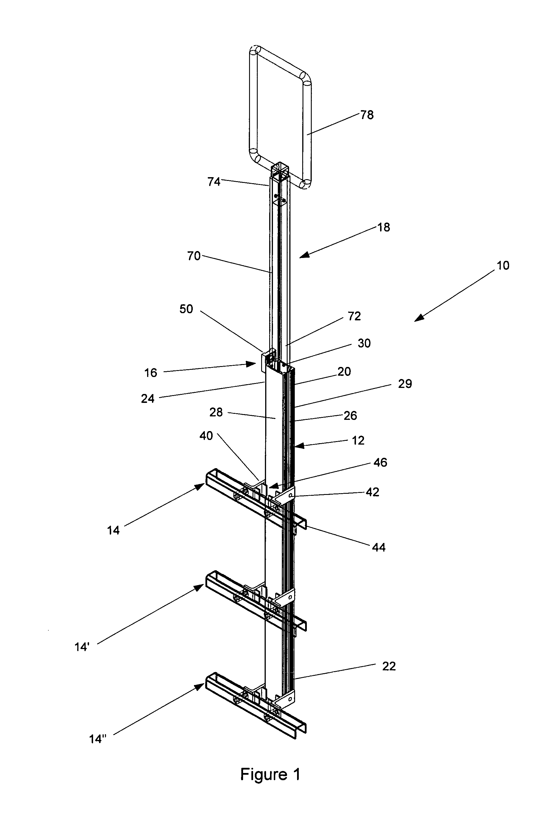
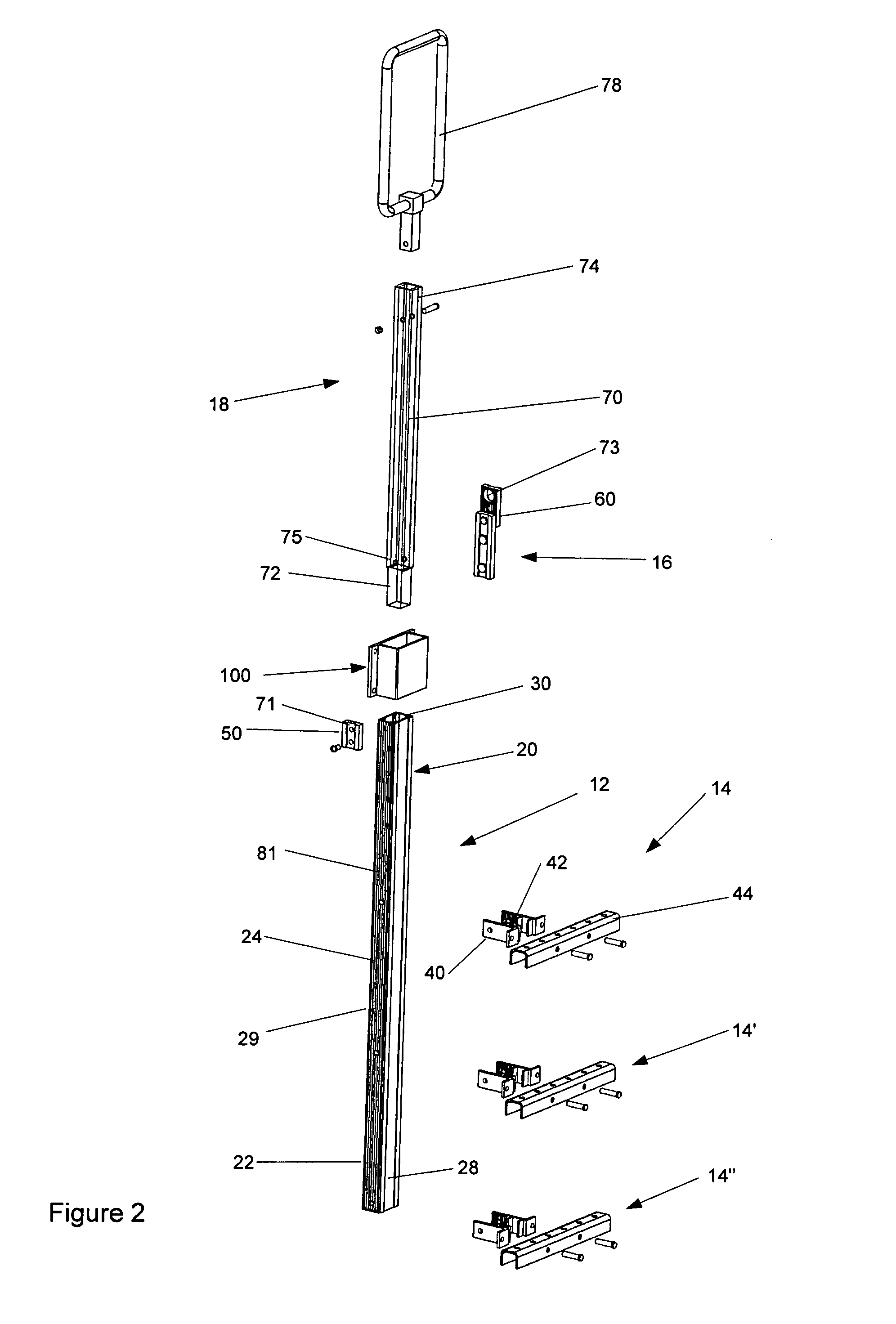
[0040]Referring now to the drawings and in particular to FIG. 1, the step ladder apparatus is shown generally at 10. The step ladder apparatus includes frame assembly 12, step assembly 14, attachment assembly 16 and handle assembly 18. The step ladder apparatus is structurally configured for ...


PUM


Abstract

A step ladder apparatus for retention within a stake pocket comprising a frame assembly a plurality of step assemblies and an attachment assembly. The attachment assembly includes a frame flange and a wedge member. The frame assembly is positioned within the stake pocket so that the frame flange overhangs one end of the stake pocket. The base of the wedge member is inserted into the stake pocket opposite the frame flange so that the wedge flange overhangs the stake pocket on a side opposite the frame flange. As a result, the flanges cooperate to substantially preclude downward movement of the frame assembly, and, in turn, removal of the frame assembly in a downward direction from the stake pocket.

Description

CROSS-REFERENCE TO RELATED APPLICATION[0001]This application claims priority from U.S. Provisional Application Ser. No. 60 / 905,872 filed Mar. 9, 2007, entitled “Light Weight, Portable truck and trailer ladder that easily attaches with the use of a locking wedge key,” the entire specification of which is hereby incorporated by reference in its entirety.BACKGROUND OF THE DISCLOSURE[0002]1. Field of the Disclosure[0003]The disclosure relates in general to step ladder apparatus, and more particularly, to a step ladder apparatus which is configured to be releasably retained within a stake pocket of a trailer of a tractor-trailer. The step ladder apparatus is designed to aid a user to climb onto the trailer. When not in use, the step ladder apparatus can be removed from the stake pocket and stowed.[0004]2. Background Art[0005]The use of step ladders is known in the art. Generally, step ladders have been provided to facilitate the climbing onto a trailer of a tractor-trailer. Indeed, a num...

Claims


Application Information

Patent Timeline
IPC IPC(8): E06C5/04
CPCE06C5/04E06C7/182E06C5/24E06C1/381
Inventor HOP, DARYL J.
Owner HOP DARYL J
Why Eureka
Eureka Blog
Learn More