
Radar apparatus

a technology of radar apparatus and antenna gain, which is applied in the direction of reradiation, measurement devices, instruments, etc., can solve the problems of affecting the performance of radar apparatus, affecting the accuracy of radar apparatus, etc., to achieve accurate and rapid judgment, improve accuracy, and improve accuracy.

Inactive Publication Date: 2007-07-24
FUJITSU GENERAL LTD
View PDF24 Cites 13 Cited by
  • Summary
  • Abstract
  • Description
  • Claims
  • Application Information

AI Technical Summary

Benefits of technology

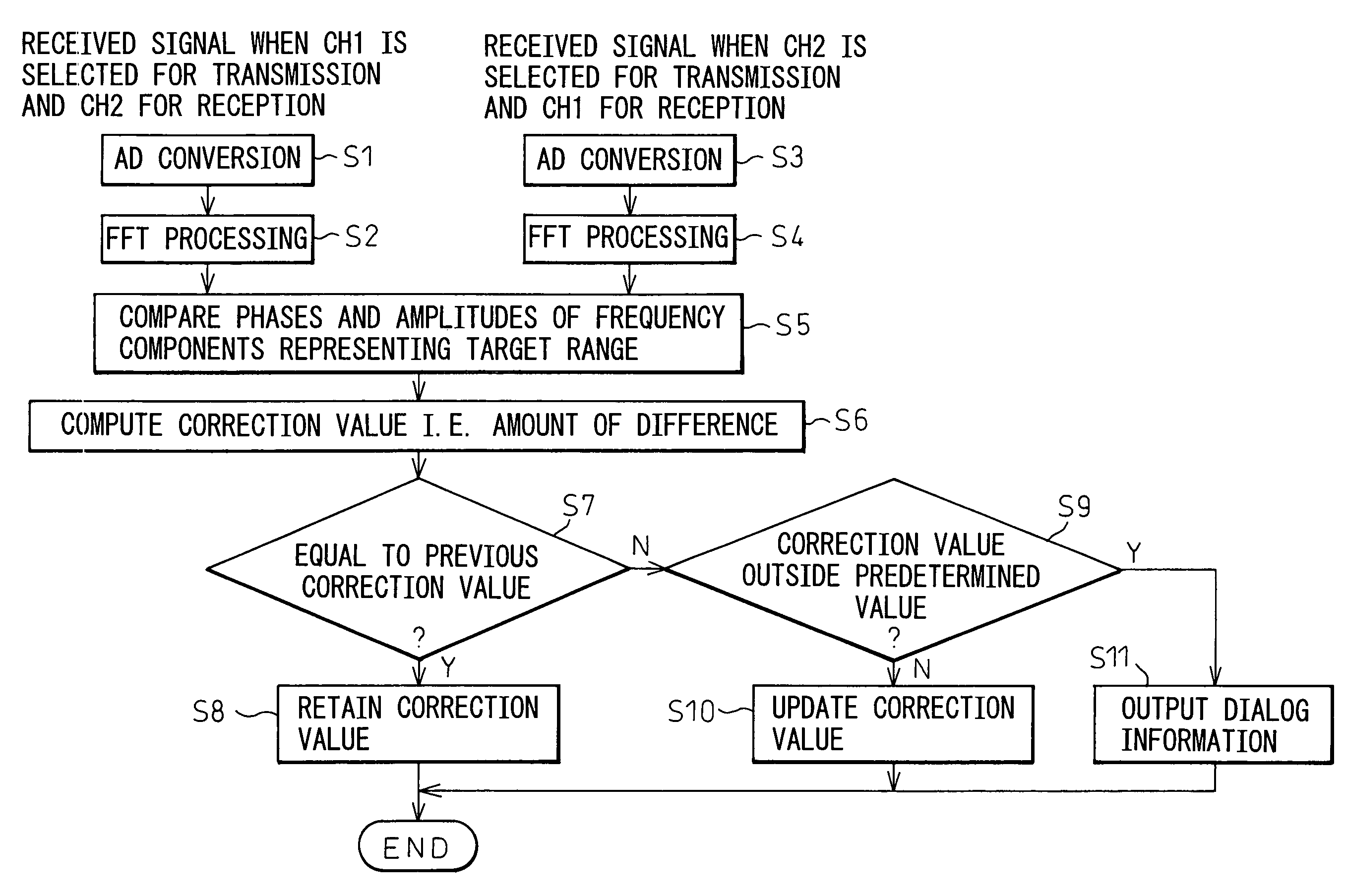
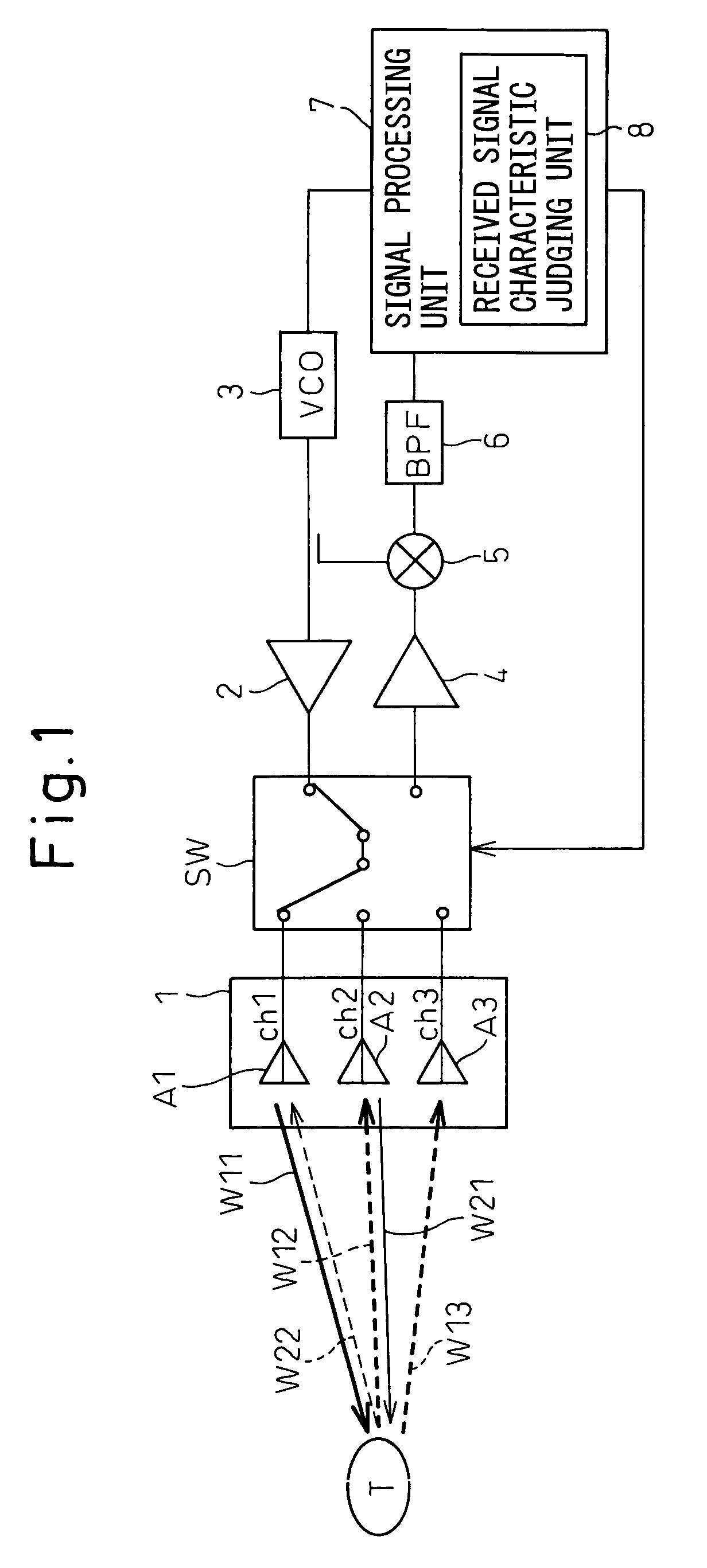
The present invention provides a radar apparatus with a plurality of antennas that can detect and measure the characteristics of reflected waves from target objects. The signal processing unit receives the reflected waves and selects two antennas to generate processing signals. The processing signals are compared and a judgment is made about any changes in the received signal based on the amplitude and phase differences between the processing signals. The signal processing unit can also make corrections to the processing signals based on a correction value computed in accordance with the change in the received signal. This allows for accurate and quick correction of any variations in the antenna characteristics during operation, ensuring high accuracy at all times. Additionally, the radar apparatus can adapt to changes in the environment, such as temperature variations, and can even make corrections in real-time.

Problems solved by technology

However, in the case of a DBF radar apparatus or the like that has a plurality of receiving antennas and performs azimuth detection by using phase information, phase shifts and variations in antenna gain among the antennas can occur due to performance differences among the plurality of antennas.
However, this approach is costly as a measure to improve product quality.
If azimuth detection is performed without correcting such phase shift, detrimental effects will result, such as a disruption of the scanning direction profile of the combined result or an increase in sidelobe level, causing a degradation of the radar apparatus performance.
However, when using the above correcting means for the phase correction, the reference signal generator and the adjusting antenna must be provided in addition to the radar apparatus itself and, if these components are incorporated into the radar apparatus, not only the size but also the cost of the apparatus increases.
Therefore, this has the problem that the phase correction cannot be performed during normal use of the radar apparatus.

Method used


Image

  • Radar apparatus
  • Radar apparatus
  • Radar apparatus

Examples


Embodiment Construction

[0041]For a better understanding of the effect to be achieved by the present invention, first the principle for measuring the range, velocity, and azimuth of a target in a previously proposed radar apparatus and the system configuration implementing it will be described in detail below.

[0042]The range from the radar apparatus to the target is denoted by R0, the spacing between two receiving antennas by L, and the azimuth angle to the target by θ. Then, the ranges R1 and R2 from the respective receiving antennas to the target are

R1=R0+(L / 2)·sin θ

R2=R0−(L / 2)·sin θ

The phase difference Δφ between the received signals at the respective receiving antennas is

Δφ=(L / λ)·sin θ

where λ is the wavelength of the received signals. Hence, the azimuth angle θ to the target is

θ=sin−1 {(λ / L)·Δφ}

Thus, the azimuth to the target is obtained from the phase difference between the received signals.

[0043]On the other hand, an FM-CW radar apparatus is one that detects target range and velocity by using a conti...


PUM


Abstract

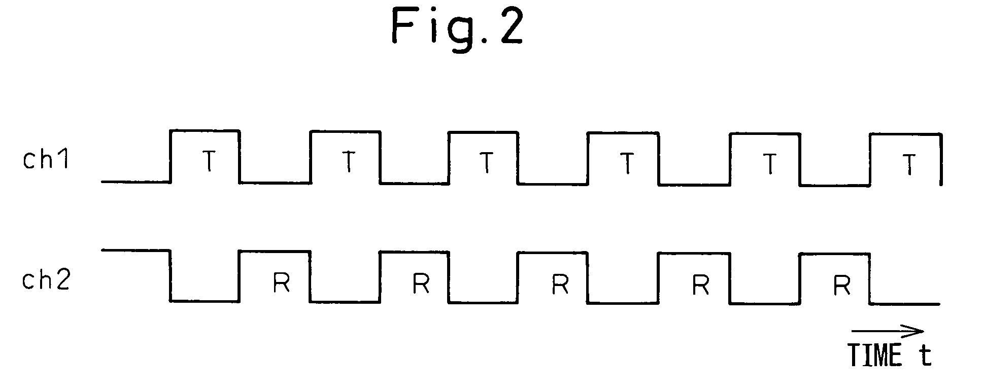
The present invention relates to a radar apparatus that uses a plurality of transmitting / receiving antennas A1-A4 and receives a reflected wave, of a transmitted wave, reflected from a target. By utilizing the property that the path of the transmitted wave from an antenna A1 and its reflected wave and the path of the transmitted wave from the next selected antenna A2 and its reflected wave share the same spatial system, and therefore that both received signals have the same characteristics in terms of frequency and phase, a judgment is made as to whether there exists any difference between the receiving characteristics of the antennas, and the received signal is corrected in accordance with the result of the judgment. It is also possible to judge the presence or absence of a change in the characteristic of each antenna, and apply a correction accordingly, even during the normal operation of the apparatus.

Description

CROSS-REFERENCE TO RELATED APPLICATION[0001]This application claims the priority of Japanese Patent Application Number 2004-176791, filed on Jun. 15, 2004.BACKGROUND OF THE INVENTION[0002]1. Field of the Invention[0003]The present invention relates to a radar apparatus equipped with a plurality of antennas each switchable between transmission and reception and, more particularly, to a radar apparatus that can accurately and quickly detect an antenna fault during normal operation, can easily make adjustments for changes in the receiving characteristics of each antenna, and can even make corrections, whenever necessary, for changes in characteristics occurring due to changes in ambient temperature.[0004]2. Description of the Related Art[0005]Traditionally, various kinds of radar apparatuses have been used to detect the azimuth, range, and velocity of a target. In recent years, radar apparatuses have come to be mounted on vehicles and used for such applications as collision warning, co...

Claims


Application Information

Patent Timeline
Patent Type & Authority Patents(United States)
IPC IPC(8): G01S7/40G01S13/58
CPCG01S7/4008G01S7/4056G01S7/4021G01S13/583
Inventor SHIMA, NOBUKAZUISAJI, OSAMU
Owner FUJITSU GENERAL LTD
Learn More